Automobile exhaust treatment equipment for pollution abatement and automobile exhaust treatment method

A vehicle exhaust and pollution control technology, which is applied in the direction of mechanical equipment, exhaust devices, noise reduction devices, etc., can solve the problems of low service life of treatment equipment filters, high cost of use, and difficulty in installation and disassembly, achieving high cost of use, The effect of extending the service life and reducing the number of replacements

Active Publication Date: 2019-02-01
WENZHOU QIFANG NEW ENERGY CO LTD
View PDF4 Cites 3 Cited by
  • Summary
  • Abstract
  • Description
  • Claims
  • Application Information

AI Technical Summary

Problems solved by technology

[0004] In order to solve the above problems, the present invention provides a vehicle exhaust gas treatment equipment and a vehicle exhaust treatment method for pollution control, which can solve the difficulties in installation and disassembly of the vehicle exhaust treatment equipment under the existing technical conditions, and the low service life of the filter screen of the treatment equipment , frequent replacement, high cost of use, etc., it can realize the function of automobile exhaust treatment, and has the advantages of convenient installation and disassembly of exhaust gas treatment equipment, long service life of filter screen and low cost of use

Method used


Image

  • Automobile exhaust treatment equipment for pollution abatement and automobile exhaust treatment method
  • Automobile exhaust treatment equipment for pollution abatement and automobile exhaust treatment method
  • Automobile exhaust treatment equipment for pollution abatement and automobile exhaust treatment method

Examples


Embodiment Construction

[0025] In order to make the technical means, creative features, goals and effects achieved by the present invention easy to understand, the present invention will be further described below in conjunction with specific illustrations. It should be noted that, in the case of no conflict, the embodiments in the present application and the features in the embodiments can be combined with each other.

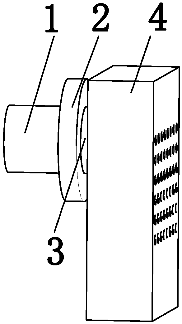
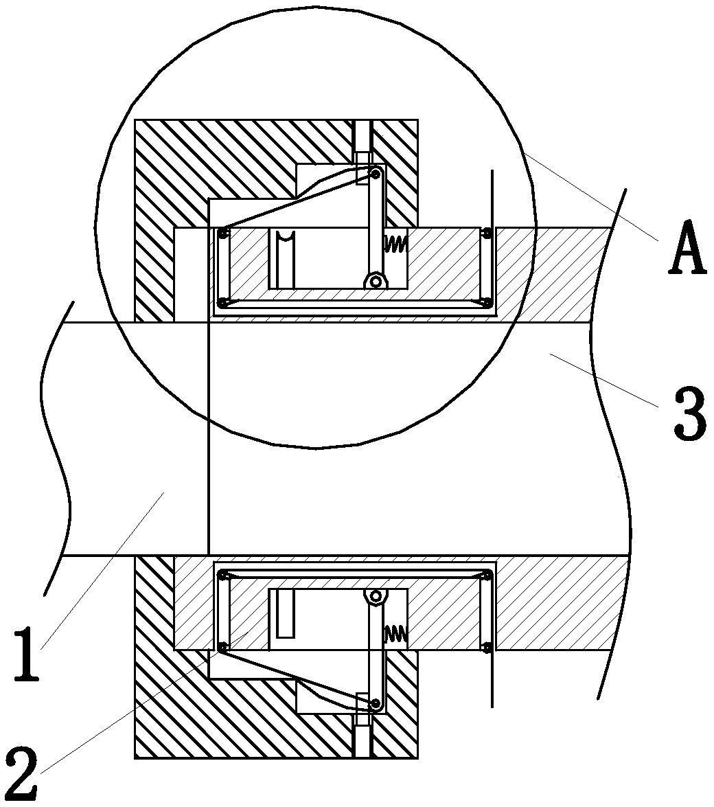
[0026] Such as Figure 1 to Figure 6 As shown, a kind of automobile tail gas treatment equipment for pollution control, including exhaust pipe 1, fixing mechanism 2, connecting pipe 3 and processing mechanism 4, described exhaust pipe 1 right side is equipped with fixing mechanism 2, and fixing mechanism 2 A connecting pipe 3 is installed on the right side, and a processing mechanism 4 is installed on the right side of the connecting pipe 3 .

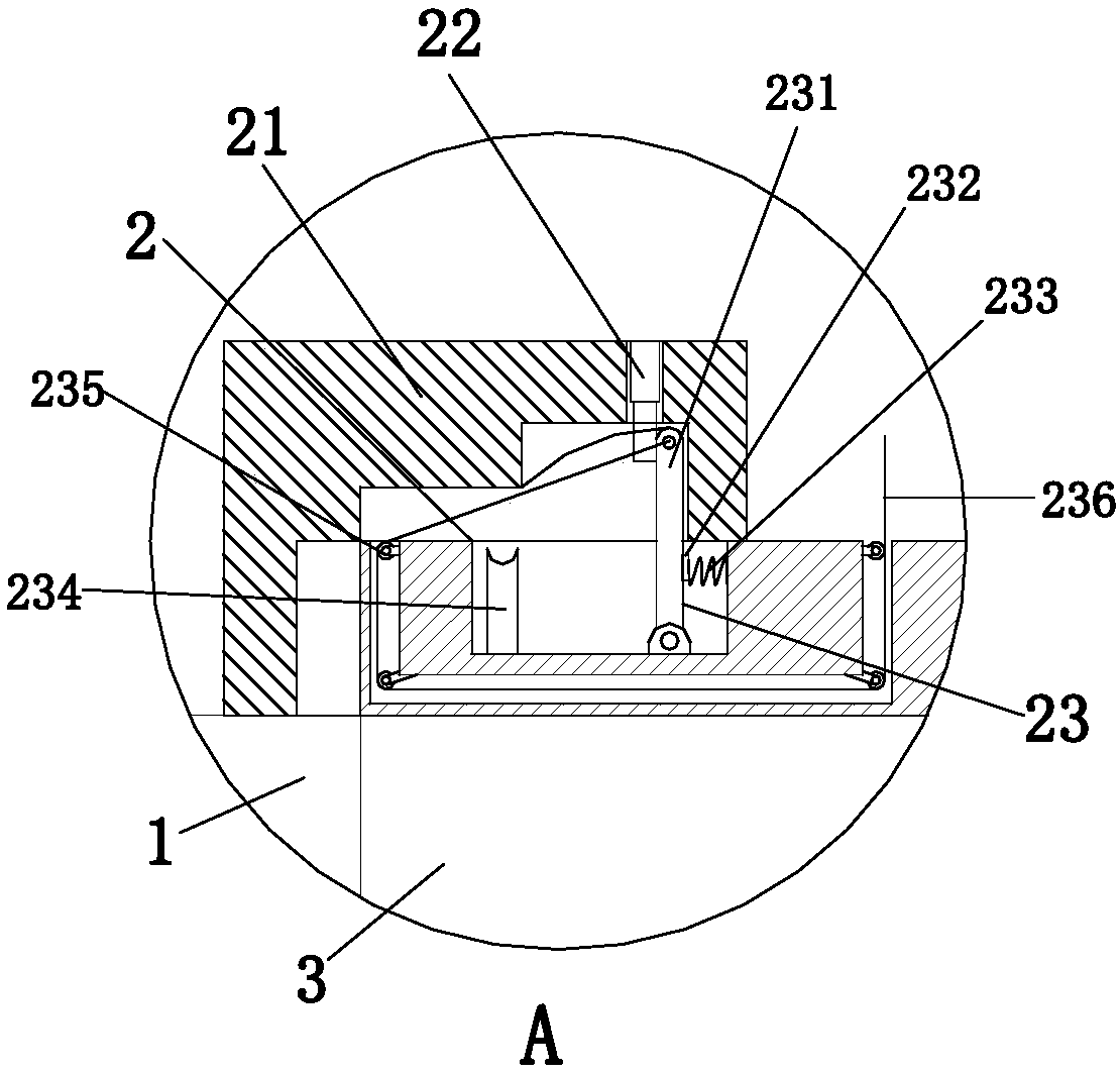
[0027]The said fixing mechanism 2 is evenly provided with three along the circumferential direction of the exhaust pipe 1. The fixing mechan...


PUM


Abstract

The invention relates to automobile exhaust treatment equipment for pollution abatement and an automobile exhaust treatment method. The automobile exhaust treatment equipment comprises an exhaust pipe, fixed mechanisms, a connecting pipe and a treatment mechanism. The fixed mechanisms are mounted on the right side of the exhaust pipe. The connecting pipe is mounted on the right side faces of the fixed mechanisms. The treatment mechanism is mounted on the right side face of the connecting pipe. The three fixed mechanisms are evenly arranged in the circumferential direction of the exhaust pipe.Each fixed mechanism comprises a fixed barrel. The fixed barrels are mounted at the right end of the side wall of the exhaust pipe. The inner side wall of each fixed barrel is in a step shape from left to right, and the step on the rightmost side of the inner side wall of each fixed barrel is of an arc structure. A limiting electric push rod is mounted on the right side of the inner side wall of each fixed barrel. According to the automobile exhaust treatment equipment for pollution abatement and the automobile exhaust treatment method, the problems that equipment mounting and demounting difficulty exists in automobile exhaust treatment equipment under the existing technical conditions, and a filter screen of the treatment equipment is short in service life, frequent in replacement and high in use cost can be solved; the function of automobile exhaust treatment can be achieved; and the advantages that the exhaust treatment equipment is convenient to mount and demount, and a filter screen is long in service life and low in use cost are achieved.

Description

technical field [0001] The invention relates to the technical field of automobile exhaust gas treatment, in particular to an automobile exhaust gas treatment equipment and an automobile exhaust gas treatment method for pollution control. Background technique [0002] Environmental pollution refers to natural or man-made destruction, the behavior of adding certain substances to the environment and exceeding the self-purification ability of the environment to cause harm. Environmental pollution includes air pollution, soil pollution, water pollution, etc., and air pollution is caused by various industries. Exhaust waste, exhaust gas emitted from people's lives, and exhaust gas emitted by ships, vehicles and other vehicles. [0003] According to statistics, tens of millions of tons of automobile exhaust are discharged into the air every year in my country. Automobile exhaust contains substances such as fixed suspended particles, carbon monoxide and aluminum. The most direct, bu...

Claims


Application Information

Patent Timeline
Patent Type & Authority Applications(China)
IPC IPC(8): F01N13/18F01N3/08
CPCF01N3/0807F01N13/18
Inventor 吴迎莉
Owner WENZHOU QIFANG NEW ENERGY CO LTD
Why Eureka
Try Eureka