Transfer structure for vehicle

A vehicle and power transmission mechanism technology, applied to vehicle components, vehicle subunit functions, transmission parts, etc., can solve problems such as excessive lubricating oil collection and oil level drop

Inactive Publication Date: 2019-02-01
MAZDA MOTOR CORP
View PDF7 Cites 2 Cited by
  • Summary
  • Abstract
  • Description
  • Claims
  • Application Information

AI Technical Summary

Problems solved by technology

[0008] Therefore, since the lubricating oil is supplied to the accommodating space through the communication hole, when the vehicle is running at

Method used


Image

  • Transfer structure for vehicle
  • Transfer structure for vehicle
  • Transfer structure for vehicle

Examples


Embodiment Construction

[0073] Hereinafter, specifics of the transfer device for a vehicle according to the present invention will be described.

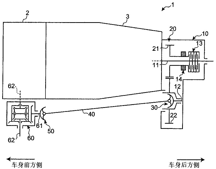
[0074] Such as figure 1 As shown, the four-wheel drive vehicle 1 loaded with the transfer device according to the embodiment of the present invention is a front-engine rear-drive (Front-engine Rear-drive) vehicle-based four-wheel drive vehicle, and the engine 2 and the transmission 3 as the driving source are centered on the axis The form extending in the front-rear direction of the vehicle body is arranged at the front part of the vehicle body.

[0075] The rear of the vehicle body of the transmission 3 is provided with a transfer device 10, and the transfer device 10 is provided with an output shaft 11 for rear wheels extending the driving force output from the transmission to the rear side of the vehicle body, and an output shaft 11 connected to the rear wheels. The output shafts 11 are arranged in parallel and output the driving force to the front whe...


PUM


Abstract

Provided is a transfer structure of a vehicle, so as to reduce the oil level of the oil storage part of the transfer device during the high-speed driving, and improve the insufficient lubrication during the low-speed driving, and the insufficient lubrication brought by unbalance of oil supply amount of helical gear. In a transfer device which comprises a driving gear, a driven gear disposed at a position lower than the driving gear, and an accommodating space receiving the gear, the lower part of the accommodating space is stored with lubrication oil. A first lubrication oil storing space anda second lubrication oil storing space, which are respectively adjacent to the accommodating space and used for storing lubrication oil, are respectively isolated from the accommodating space througha first isolating wall and a second isolating wall. The first and the second isolating wall are respectively provided with a through hole communicating with the accommodating space under the state oflimiting flow. The first isolating wall is set to be below the regulated oil level, and the second isolating wall is set to be above the oil level.

Description

technical field [0001] The invention relates to a transfer structure loaded on a four-wheel drive vehicle. Background technique [0002] As a four-wheel-drive vehicle, a structure is known in which a drive source such as an engine and a transmission are arranged at the front of the vehicle body in such a manner that the axis extends in the front-rear direction of the vehicle body, and a transfer device is provided so that the driving force output from the transmission passes through the rear of the vehicle body. The output shaft for the rear wheels and the differential device for the rear wheels transmit the driving force output to the front wheels as the auxiliary driving wheels to the rear wheels as the main drive wheels, and the driving force extracted by the transfer device is passed to the vehicle body The output shaft for the front wheels extending forward and the differential for the front wheels are transmitted to the front wheels, and the front wheels can also be dr...

Claims


Application Information

Patent Timeline
IPC IPC(8): F16H57/04B60K17/344
CPCB60K17/344F16H57/0452F16H57/0453F16H57/0447F16H57/0457F16H57/0423B60Y2306/03B60K17/35B60K23/0808B60K2023/0825F16H2057/02043B60K17/3467F16H57/0483
Inventor 大川裕三野口慈仁原泽涉
Owner MAZDA MOTOR CORP
Why Eureka
Try Eureka