
Track and road obstacle detecting method

An obstacle detection and obstacle detection technology, applied in the field of track and road obstacle detection, can solve the problems of lack of early warning ability, short detection distance, and identification of obstacles, so as to achieve early warning safety, accurate identification of obstacles, Guarantee the effect of the warning function

Active Publication Date: 2019-02-01
ZHUZHOU ELECTRIC LOCOMOTIVE CO
View PDF11 Cites 32 Cited by
  • Summary
  • Abstract
  • Description
  • Claims
  • Application Information

AI Technical Summary

Problems solved by technology

[0002] Domestic mainstream obstacle detection technology is still in its infancy. Now the main rail transit obstacle detection technology still stays at the front end of the rail vehicle by installing a contact obstacle detection device. This technology detects through the mechanical method of touch. The detection distance is short, and there is no early warning capability
However, the current radar detection technology is not mature enough, especially when driving on a turning or a slope, its detection accuracy and accuracy cannot meet the obstacle detection requirements of road traffic
In addition, the number of laser scanning points is limited, and the scanning points are uneven and sparse, which will easily cause the vehicle to be unable to easily identify obstacles in places where the point cloud is relatively sparse, and the size of obstacles cannot be qualitatively estimated.
At the same time, the millimeter-wave radar is not mature, and the accuracy and accuracy of long-distance detection are difficult to meet the requirements of the automatic driving system, and the cycle of upgrading a single radar system is long

Method used


Image

  • Track and road obstacle detecting method
  • Track and road obstacle detecting method
  • Track and road obstacle detecting method

Examples


Embodiment Construction

[0018] The principle of the invention is prepared as follows:

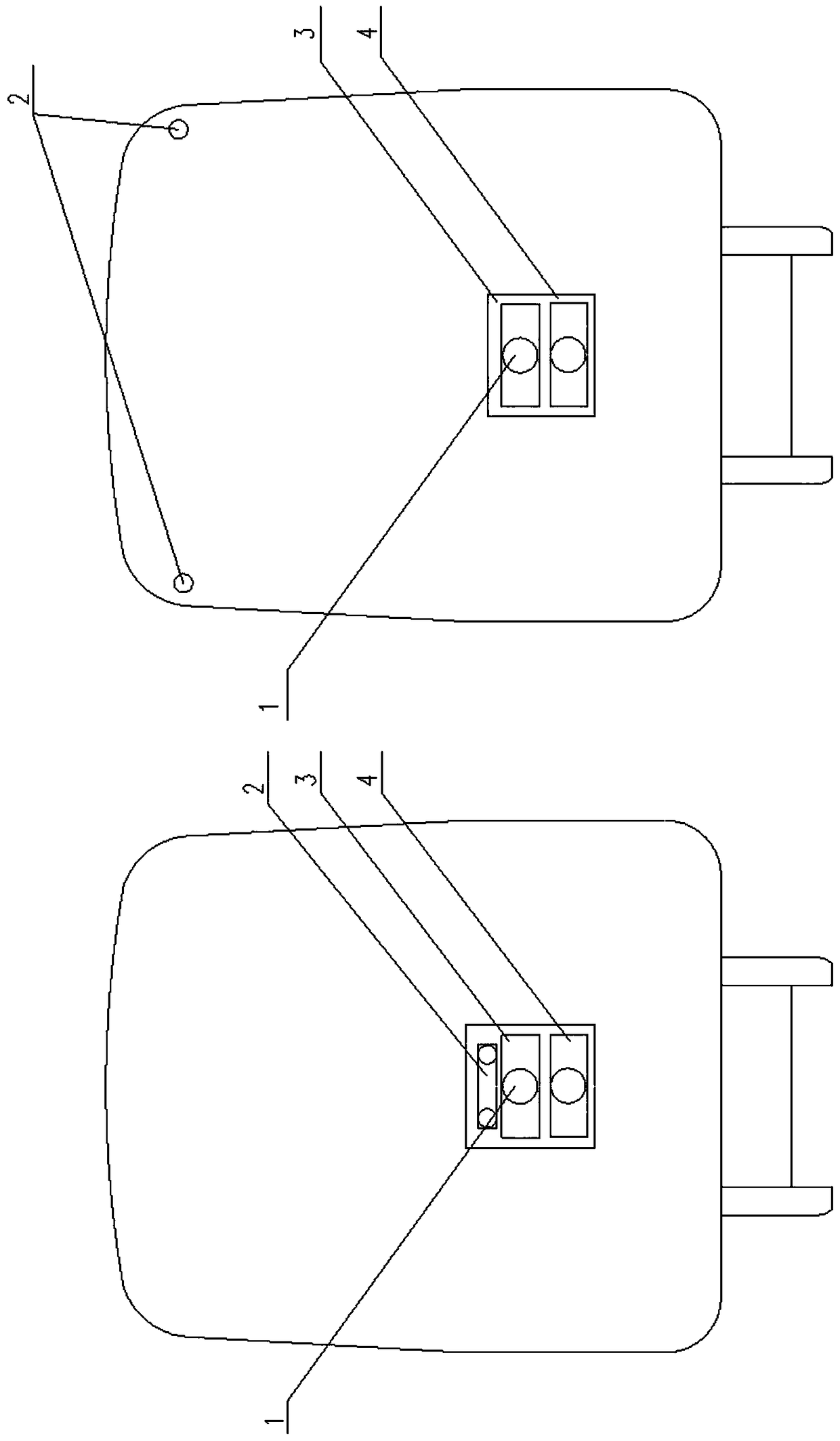
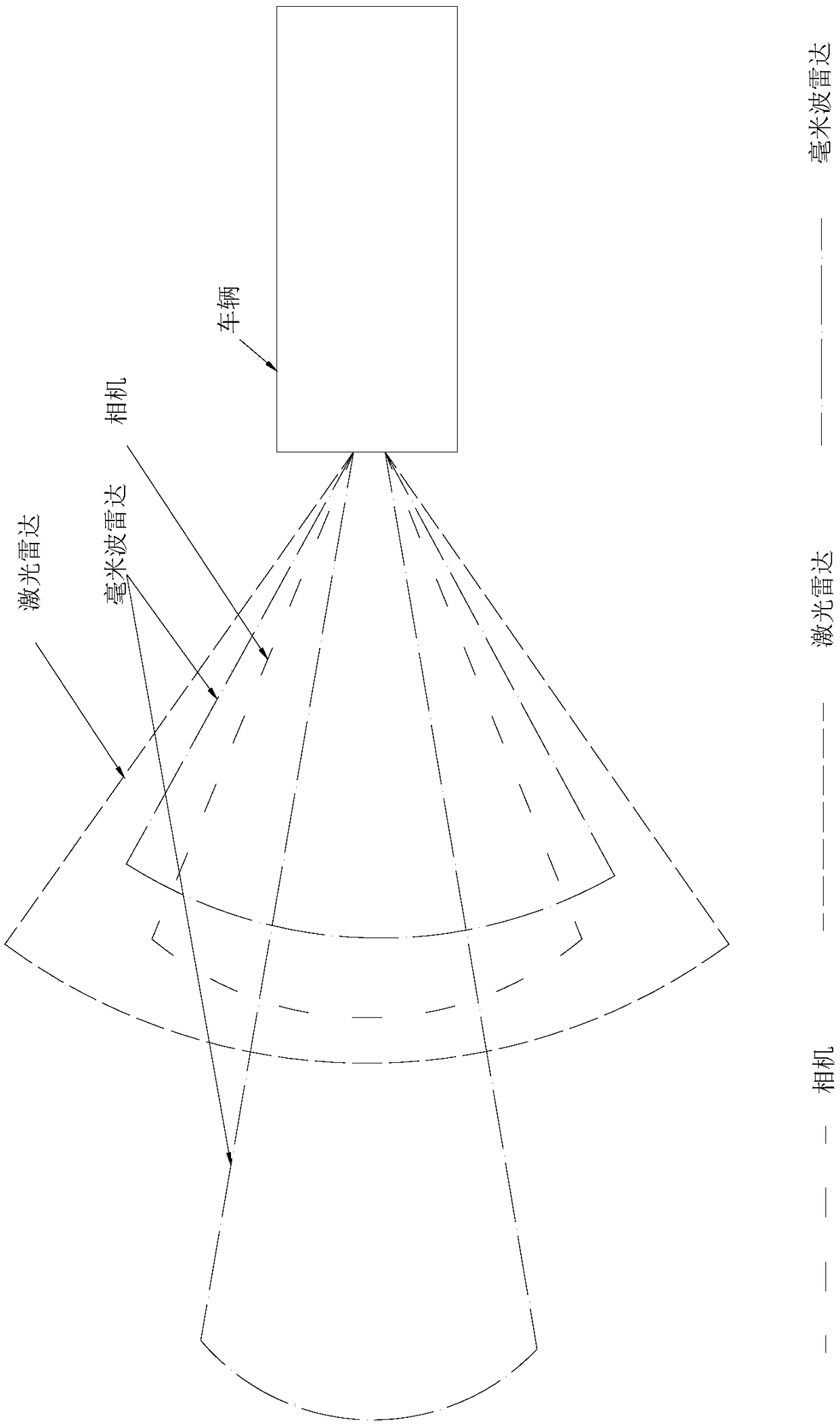
[0019] On a rail vehicle, the lidar system 1, the camera system 2, the millimeter wave radar system 3 and the on-board system 4 are figure 1 Installed at the end of the vehicle. Laser radar system 1, camera system 2, millimeter wave radar system 3 detection range such as figure 2 shown.

[0020] Millimeter wave detection technology

[0021] Millimeter wave radar sensors use millimeter waves. Usually millimeter wave refers to the 30-300GHz frequency domain (wavelength 1-10mm). The wavelength of the millimeter wave is between the centimeter wave and the light wave, so the millimeter wave has the advantages of microwave guidance and photoelectric guidance. Compared with centimeter-wave radar, millimeter-wave radar has the characteristics of small size, easy integration and high spatial resolution. The principle of ranging is the same as that of general radar, that is, sending out radio waves (radar waves), the...


PUM


Abstract

The invention discloses a track and a road obstacle detecting method. The method comprises the following steps: A. obtaining an image of the front of a vehicle through a monocular camera or multiple cameras; B. transmitting and receiving an optical signal by a millimeter-wave device and a laser device to obtain a 2D point cloud image and a 2D spectrogram; C. performing a multi-look processing on the image, taking a video system as a medium, and analyzing and matching a laser radar with the video system by using a focal plane array; for a millimeter-wave radar, matching the video system with amillimeter-wave radar system by a data preprocessing and an edge matching method to complete the pixel level fusion of the laser radar, the millimeter-wave radar and the video system; performing sequence analysis on the acquired image, filtering a multi-radar system and the video system, and matching images acquired by the millimeter-wave radar and the laser radar with an original image; and D. marking obstacles. The track and the road obstacle detecting method can accurately identify the obstacles, has certain early warning functions, and can simultaneously ensure accuracy and early warning functions.

Description

technical field [0001] The invention belongs to the field of transportation, and in particular relates to a detection method for track and road obstacles. Background technique [0002] Domestic mainstream obstacle detection technology is still in its infancy. Now the main rail transit obstacle detection technology still stays at the front end of the rail vehicle by installing a contact obstacle detection device. This technology detects through the mechanical method of touch. The detection distance is short, and it does not have early warning capabilities. However, the current radar detection technology is not yet mature enough, especially when driving on turns and slopes, its detection accuracy and accuracy cannot meet the obstacle detection requirements of road traffic. In addition, the number of laser scanning points is limited, and the scanning points are uneven and sparse, which may easily cause the vehicle to be unable to easily identify obstacles in places where the p...

Claims


Application Information

Patent Timeline
IPC IPC(8): G01S13/86
CPCG01S13/865G01S13/867G01S7/417G01S13/862G01S13/931G01S13/87G01S2013/9328G01S2013/93271G01S17/931G01S17/86G01S7/4802
Inventor 王睿王虎高屈海洋陈勇李希宁
Owner ZHUZHOU ELECTRIC LOCOMOTIVE CO
Learn More