Head display device

A technology for head-mounted display equipment and connecting parts, which is applied to optical components, optics, instruments, etc., can solve the problems of poor wearing stability and wearing experience of users, difficult modularization of head-mounted display equipment, complex structure, etc., and achieves convenient and fast connection , Simplify the setting of the interface, and reduce the effect of setting the connection interface

Pending Publication Date: 2019-02-01
BEIJING 7INVENSUN TECH
View PDF0 Cites 7 Cited by
  • Summary
  • Abstract
  • Description
  • Claims
  • Application Information

AI Technical Summary

Problems solved by technology

In the existing head-mounted display devices that can realize virtual display and enhanced display at the same time, each s

Method used


Image

  • Head display device
  • Head display device
  • Head display device

Examples


Embodiment Construction

[0028] The present invention will be further described in detail below in conjunction with the accompanying drawings and embodiments. It should be understood that the specific embodiments described here are only used to explain the present invention, but not to limit the present invention. In addition, it should be noted that, for the convenience of description, only some structures related to the present invention are shown in the drawings but not all structures.

[0029] In this embodiment, each component in the head-mounted display device is described with the posture and posture of the head-mounted display device in use, that is, the upper end of a component is the end of the part away from the ground when the wearer is wearing the head-mounted display device. The lower end of a part is the end of the part facing the ground in the worn state.

[0030] In the description of the present invention, unless otherwise clearly specified and limited, the terms "connected", "conne...


PUM


Abstract

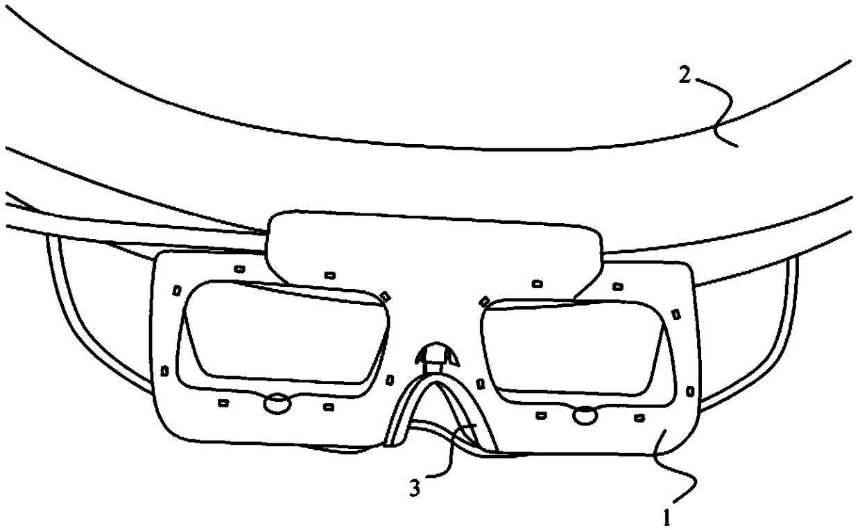
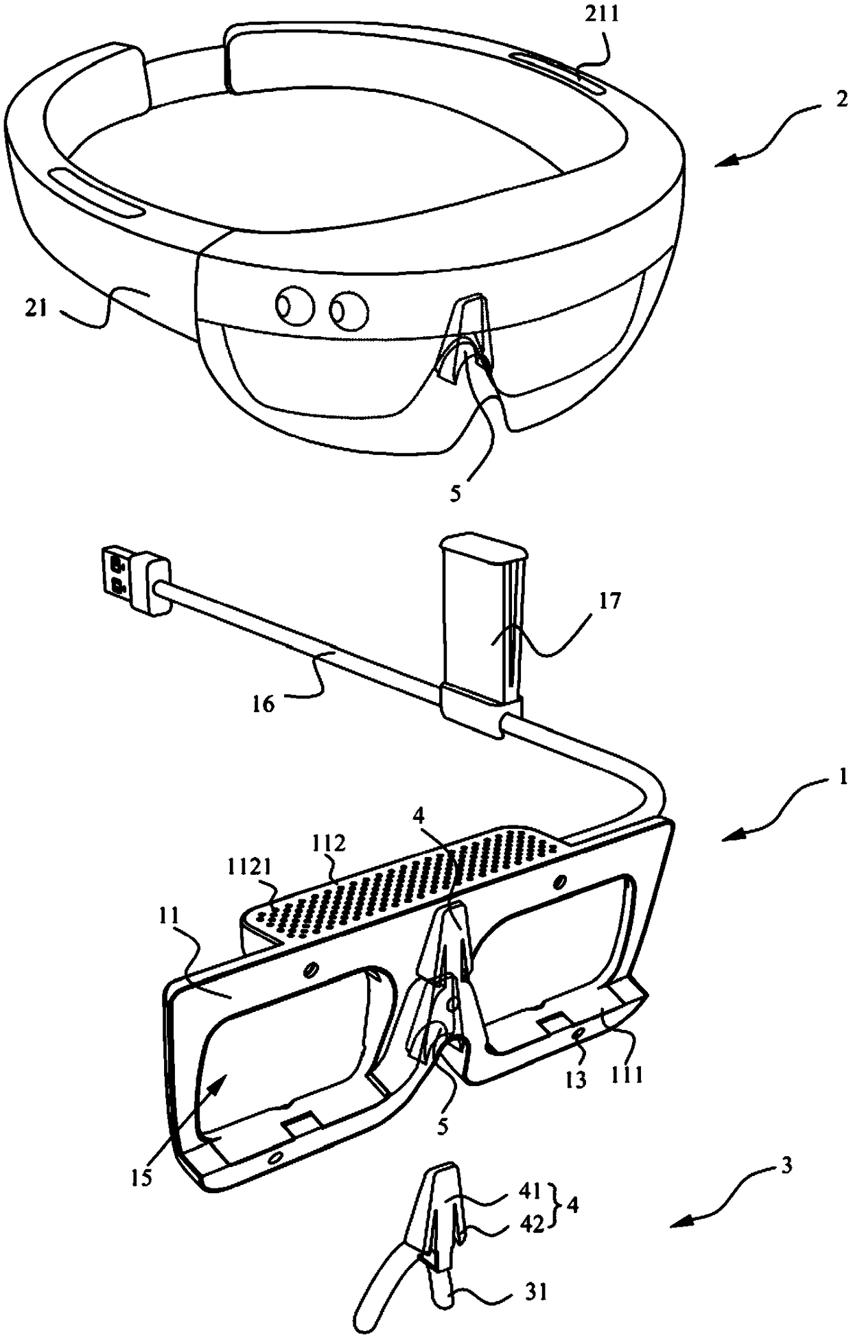
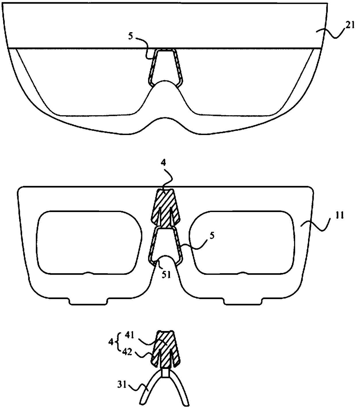
The invention belongs to the technical field of intelligent wearable equipment, and particularly discloses a head display device. The head display device comprises a head display body, an eyeball tracking module and a supporting part, wherein the head display body is used for holding the head display device on the head of a wearer; the eyeball tracking module and the supporting part are provided with a first connecting part separately, and a second connecting part is arranged on the eyeball tracking module and the head display body separately; the first connecting part of the supporting part can be detachably connected with the second connecting part on the eyeball tracking module or the second connecting part on the head display body; and the first connecting part on the eyeball trackingmodule can be detachably connected with the second connecting part on the head display body. According to the head display device provided by the invention, the modular design and use of the head display device are improved, so that the head display device can be installed conveniently, and the wearing experience of the wearer can be improved.

Description


Claims


Application Information

Patent Timeline
Owner BEIJING 7INVENSUN TECH
Why Eureka
Try Eureka