
Stroboscopic clock and control method thereof

A clock control and control method technology, which is applied to clocks, electronic timers, instruments, etc., can solve the problems of short viewing distance and less visible surface of the clock, and achieve the effects of simple structure, wide application range and low manufacturing cost.

Pending Publication Date: 2019-02-01
顾小果
View PDF0 Cites 0 Cited by
  • Summary
  • Abstract
  • Description
  • Claims
  • Application Information

AI Technical Summary

Problems solved by technology

[0005] The object of the present invention is to provide a stroboscopic clock and its control method to solve the problems of the existing clocks with few visible surfaces and short visual distance

Method used


Image

  • Stroboscopic clock and control method thereof
  • Stroboscopic clock and control method thereof
  • Stroboscopic clock and control method thereof

Examples


Embodiment Construction

[0030] The strobe clock and its control method of the present invention will be further described in detail with specific embodiments below in conjunction with the accompanying drawings. It should be understood that the following examples are only used to illustrate the present invention but not to limit the scope of the present invention.

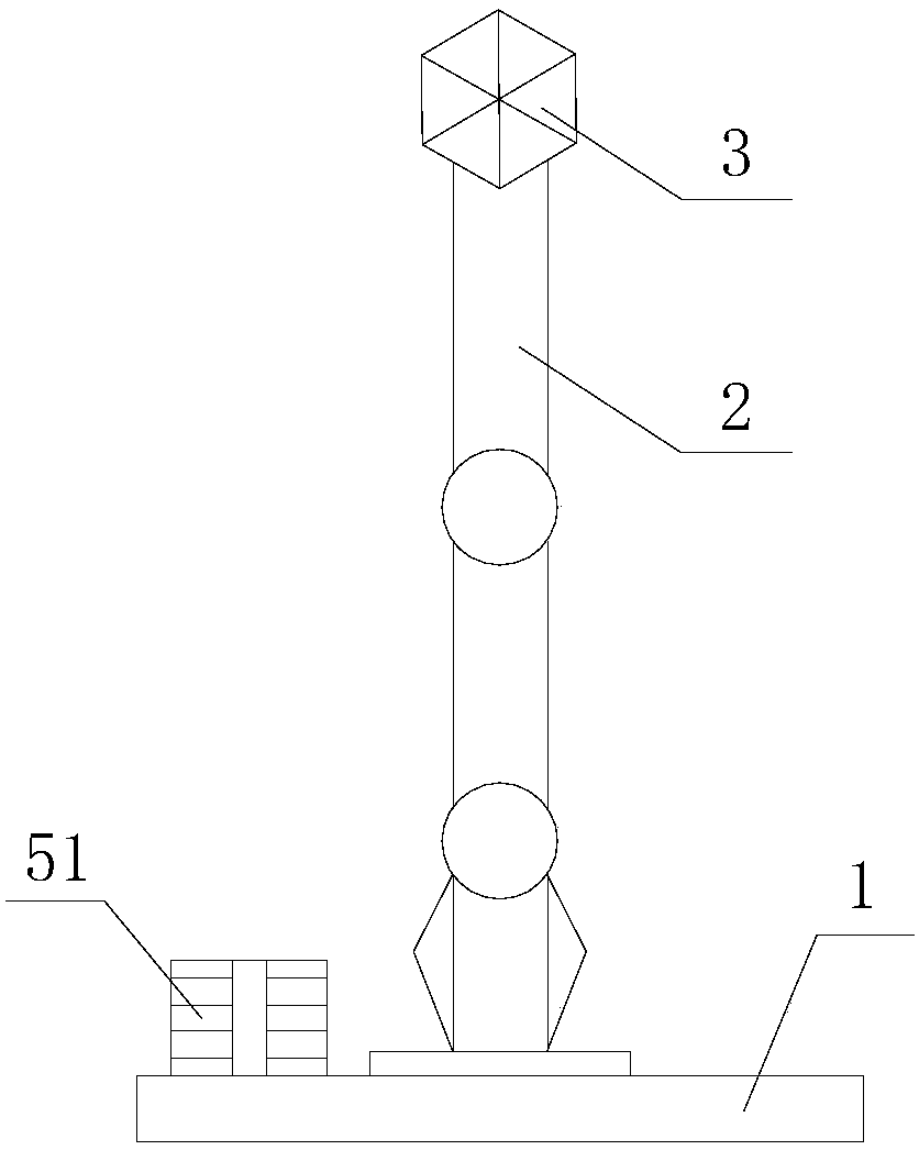
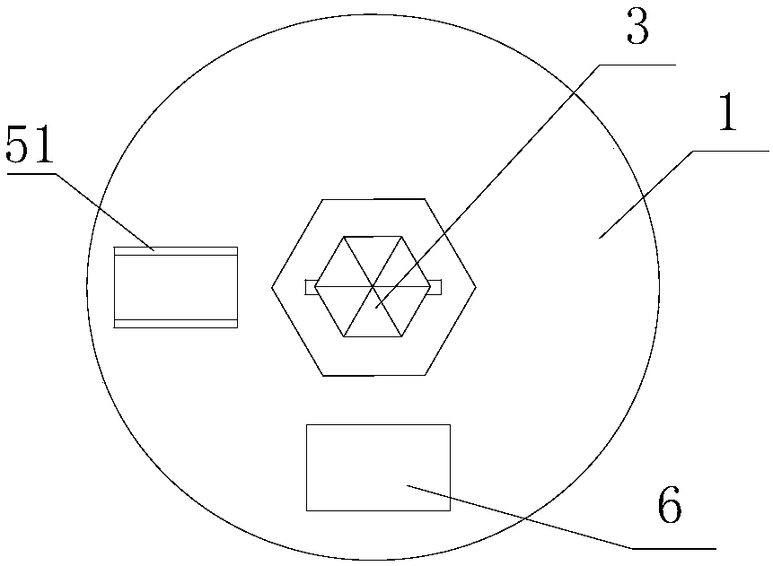
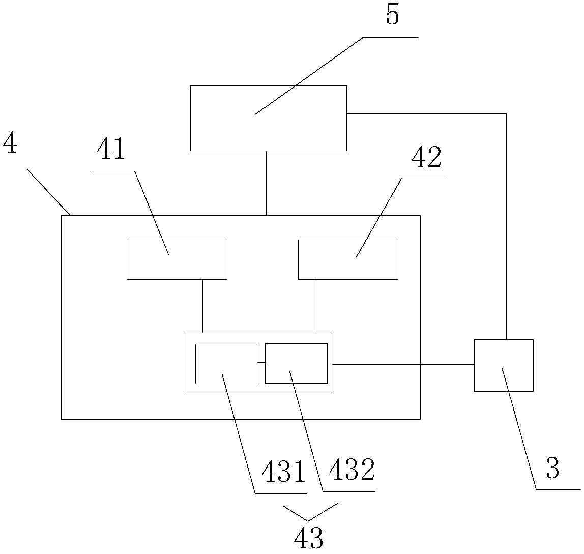
[0031] Such as Figure 1-3 As shown, it is a strobe clock of the present invention, which includes a base 1, a support column 2 arranged on the base 1, and a light-emitting unit 3 located on the top of the support column 2. The inside of the base 1 is provided with a clock control system 4. The base 1 is provided with a power supply system 5, the light emitting unit 3 is connected to the power supply system 5 through a cable, the clock control system 4 is connected to the power supply system 5 through a cable, the clock control system 4 is connected to the light emitting Unit 3 is connected by cable, and described clock control system 4 c...


PUM


Abstract

The invention discloses a stroboscopic clock, comprising a base, a support column arranged on the base, and a light-emitting unit arranged on the top of the support column. A clock control system is arranged inside the base. A power supply system is arranged on the base. The light-emitting unit and the power supply system are connected by a cable. The clock control system and the power supply system are connected by a cable. The clock control system and the light-emitting unit are connected by a cable. The clock control system includes a clock unit module, a stroboscopic module and a microprocessor module. The clock unit module is used to pass a reference time signal to the microprocessor module. The stroboscopic module is used to transmit a stroboscopic signal to the microprocessor module. The microprocessor module is configured to receive the time signal of the clock unit module and the stroboscopic signal of the stroboscopic module, and transmit the signals to the light-emitting unit after converting. The invention also discloses a control method of the above stroboscopic clock. The beneficial effects by adopting the above structure and control method are as follows: 360-degreeomni-directional visualization is achieved, and the distance is long.

Description

technical field [0001] The invention belongs to the technical field of clocks, and in particular relates to a strobe clock and a control method thereof. Background technique [0002] Although watches and mobile phones have become very popular. However, in special situations or geographic locations, it is sometimes urgent and necessary to know the current time. Therefore clocks are usually set on special occasions so that people can get the current time accurately. [0003] Traditional clocks use hour and minute hands to indicate time. No matter how big the clock face is, the viewing distance is very limited. In the 1960s and 1970s, the electronic clock was invented, and the time was displayed with luminous numbers, which greatly improved the viewing distance. However, due to the limitation of font size, the visual distance cannot be made very far. And above-mentioned two kinds of clocks have only one visible surface. Therefore, in the waiting room of the airport, the wa...

Claims


Application Information

Patent Timeline
Patent Type & Authority Applications(China)
IPC IPC(8): G04G11/00G04G19/10
CPCG04G11/00G04G19/10
Inventor 顾小果
Owner 顾小果
Learn More