
Method and device for controlling reduction power supply based on voltage limitation and current stack limitation

A technology of voltage limiting and limiting layer, applied in control/regulating systems, regulating electrical variables, instruments, etc., can solve problems such as equipment downtime, user losses, and voltage steep rises and drops.

Active Publication Date: 2020-04-21
SICHUAN INJET ELECTRIC CO LTD
View PDF4 Cites 0 Cited by
  • Summary
  • Abstract
  • Description
  • Claims
  • Application Information

AI Technical Summary

Problems solved by technology

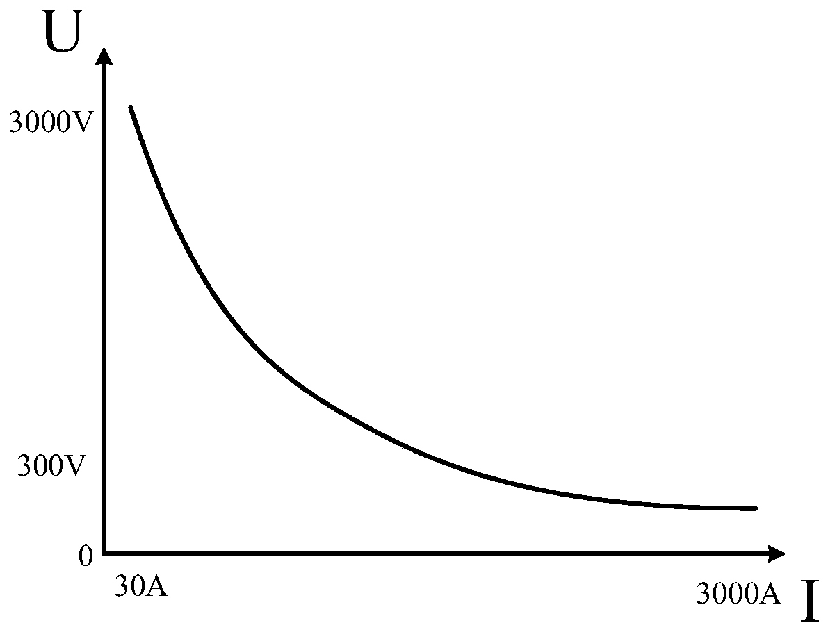
[0007] 1. During the growth process, due to pressure, airflow and other process reasons, cracked rods and short rods (that is, the resistivity of silicon rods suddenly increase or decrease), because the reduction power supply is controlled by constant current, it is bound to cause voltage steepness in a short time. The situation of steep decline;
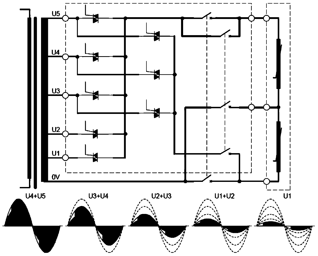
[0008] 2. Because the restoration power supply adopts multi-channel winding and multi-level voltage lamination control, because the increase and decrease of the output voltage of the double closed loop (constant current limiting voltage) will cause the restoration power supply to switch between multiple levels frequently, which will lead to the limitation of the limit loop. Point offset, thus affecting the constant current output;
[0009] 3. The relationship between the output voltage and current of the main transformer winding is low-voltage high-current, high-voltage low-current, and the specific output circuit is also protected by a corresponding thyristor-level fast-melt, and the polysilicon load resistance suddenly increases from small to small in a short period of time. When it is further reduced, the output voltage will inevitably return from the low-voltage layer to the high-voltage layer and then to the lower layer. The constant output current may cause the high-voltage layer to fuse quickly, and the thyristor will be damaged by overcurrent to stop the equipment and cause user losses.

Method used


Image

  • Method and device for controlling reduction power supply based on voltage limitation and current stack limitation
  • Method and device for controlling reduction power supply based on voltage limitation and current stack limitation
  • Method and device for controlling reduction power supply based on voltage limitation and current stack limitation

Examples


Embodiment Construction

[0035] In the following, the present invention will be further described in detail in conjunction with the accompanying drawings and embodiments, so as to make the purpose, technical solutions and advantages of the present invention more clear. It should be understood that the specific embodiments described here are only used to explain the present invention, not to limit the present invention.

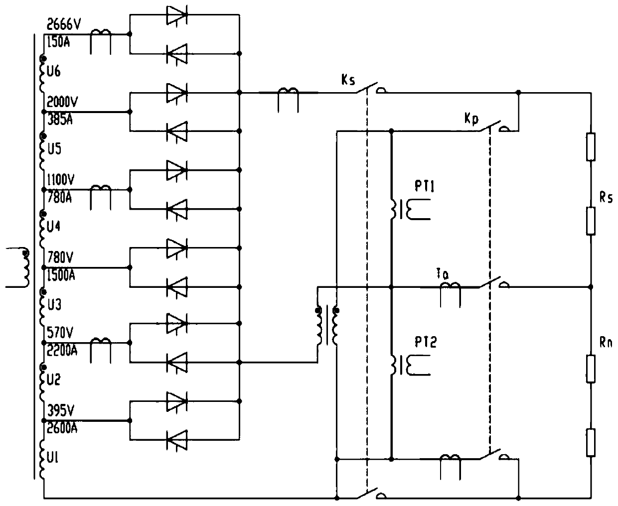
[0036] image 3 A control loop with a voltage limiting loop is shown according to an exemplary embodiment of the present invention, through which a PID controller (proportional-integral-derivative controller) controls the method of restoring power based on voltage limiting and current stack limiting mainly including voltage Limiting Process and Current Stack Limiting Process.

[0037] Such as Figure 4 As shown, the voltage limiting process according to the exemplary embodiment of the present invention mainly includes the following steps:

[0038] Step 101: During the operation of ...


PUM


Abstract

The invention discloses a method and device for controlling the restoration power supply based on voltage limitation and current stack limitation, which can avoid the situation of returning from the low layer to the high layer during the operation process, prevent the breakdown of the fast fuse and the thyristor during the growth process of polysilicon, and Prevent the output voltage from rising and falling sharply. The method includes: on a control loop with a voltage limiting loop, the PID controller controls the voltage limiting state of the restoring power supply through a voltage limiting process, and / or controls the PID output value of the restoring power supply through a current cascading limiting process.

Description

technical field [0001] The invention relates to the technical field of reduction power supply control, in particular to a method and device for controlling the reduction power supply based on voltage limitation and current stack limitation. Background technique [0002] The demand for polysilicon mainly comes from semiconductors and solar cells. According to different purity requirements, it is divided into electronic grade and solar grade. The production technologies of polysilicon are mainly improved Siemens method and silane method. The Siemens method produces columnar polysilicon by vapor deposition. This process processes industrial silicon into SiHCl, and then makes SiHCl 3 in H 2 Polysilicon is obtained by reduction deposition in a reduction furnace in an atmosphere. Tail gas H from the reduction furnace 2 , SiHCl 3 and HCl after separation and recycling. The polysilicon reaction vessel (reduction furnace) is sealed, and the silicon rod is heated by electricity...

Claims


Application Information

Patent Timeline
Patent Type & Authority Patents(China)
IPC IPC(8): G05F1/56
CPCG05F1/561
Inventor 唐亮奉亮谭兵
Owner SICHUAN INJET ELECTRIC CO LTD
Learn More