Integrated vending machine and working method thereof

A vending machine and cargo channel technology, applied in the field of integrated vending machines, can solve the problems of low strength, occupying the upper and lower space of the vending machine, and unable to place machines, etc., and achieves strong thermal insulation performance, thin box thickness, and improve production The effect of efficiency

Inactive Publication Date: 2019-02-01
JIANGYIN WANYUAN ELECTRONICS TECH CO LTD
View PDF7 Cites 1 Cited by
  • Summary
  • Abstract
  • Description
  • Claims
  • Application Information

AI Technical Summary

Problems solved by technology

[0005] 1. In the current vending machine industry, the body of the vending machine is generally made by welding the box and plugging the insulation board, but the way of welding the box will make the production efficiency of the machine low, and the inner wall of the machine is prone to streaks, which affects the appearance of the machine; In addition, the whole body of the welded box body with plugged insulation board is thicker and heavier, which affects the quality of the vending machine; at the same time, the sealing performance of the insulation board and the inner wall of the box is not strong, resulting in poor heat insulation performance of the vending machine
[0006] 2. In the past, each vending machine needed a control system to control, and multiple vending machines needed multiple control systems, which increased the floor space of the vending machine and could not place more machines
[0007] 3. The motor of the crawler aisle is fixed vertically on the rear side of the crawler aisle, and the vertical motor occupies the upper and lower space in the vending machine, so that no more crawler aisles can be placed inside the vending machine
[0008] 4. In the past, the weight of the lifting platform was large, the strength was not high, and the service life was not long

Method used


Image

  • Integrated vending machine and working method thereof
  • Integrated vending machine and working method thereof
  • Integrated vending machine and working method thereof

Examples


Embodiment Construction

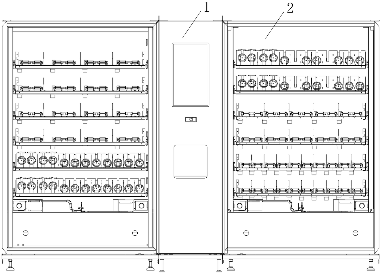
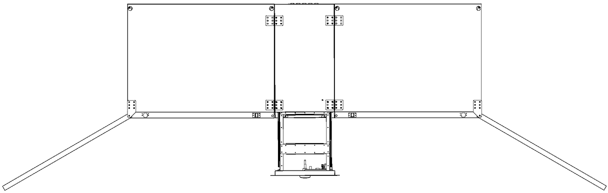
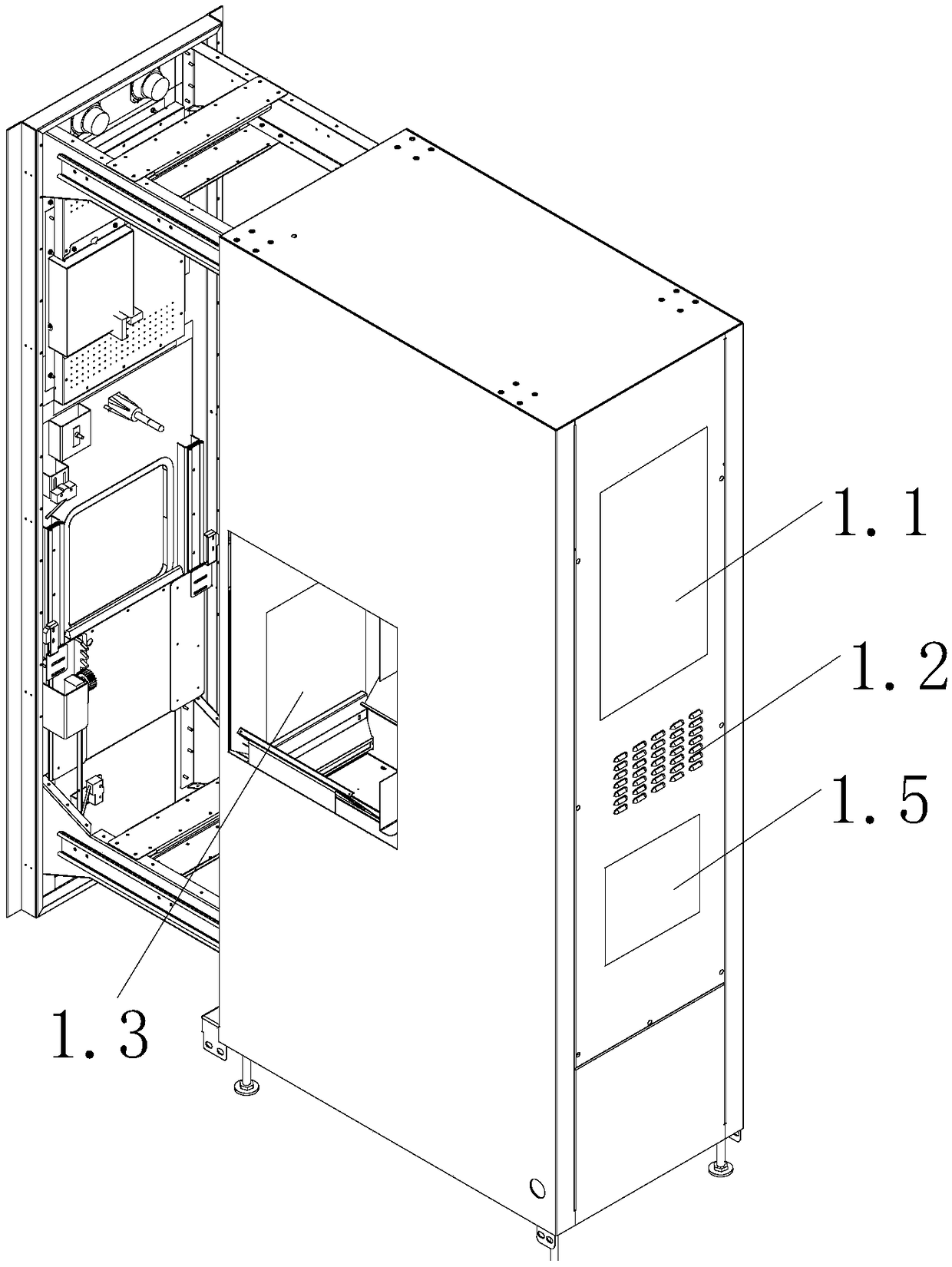
[0033] see Figure 1 to Figure 11 , The present invention relates to a comprehensive vending machine, comprising a central control box assembly 1 in the middle and a vending machine body 2 on the left and right sides.

[0034]The central control box assembly 1 is equipped with a control system inside, and the control system is used to obtain product information that customers need to purchase, and simultaneously control the shipment of vending machines on the left and right sides. The front side of the central control box assembly 1 is provided with Touch screen 1.1, and commodity button 1.2 can also be set under touch screen 1.1, and commodity button 1.2 can play the effect of standby selection commodity, and the left and right sides of described central control box component 1 are provided with a central control box inlet 1.3 respectively, and described The central control box inlet 1.3 is connected with the vending machine outlet 2.4 of the vending machine body 2, and is us...


PUM


Abstract

The invention relates to an integrated vending machine and a working method thereof, wherein a central control box controls two vending machines at the same time, so that the space for the vending machine can be saved and more goods can be sold. A motor is laterally fixed at one side of track-type goods passages, and according to the lateral fixation, the vertical space in the vending machine canbe saved, so that more track-type goods passages can be arranged inside the vending machine. A lifting platform is constructed by splicing a lateral plate and vertical plates on the inner and outer sides. A plurality of through holes are formed in the lateral plate, which can reduce the total weight of the lifting platform. A plurality of connecting rods are arranged from left to right between thevertical plates, which can increase the strength. The two vertical plates are respectively arranged with a mounting port near the outlet of the vending machine. A sensor can be fixed in the mountingport, which can sense that goods being moved to a tray of the central control box assembly through the outlet of the vending machine.

Description

technical field [0001] The invention relates to a comprehensive vending machine and a working method thereof, belonging to the technical field of vending machines. Background technique [0002] Vending machine is a common equipment for commercial automation. It is not limited by time and place. It can save manpower and facilitate transactions. It is a new form of commercial retail and is also known as a 24-hour miniature supermarket. The current vending machines are mainly divided into three types: beverage vending machines, food vending machines, and comprehensive vending machines. [0003] The integrated vending machine has the functions of spring machine and crawler machine at the same time, and goods can be purchased through the spring machine cargo lane and the crawler cargo lane. [0004] But there are following defectives in present integrated automatic vending machine: [0005] 1. In the current vending machine industry, the body of the vending machine is generally...

Claims


Application Information

Patent Timeline
Patent Type & Authority Applications(China)
IPC IPC(8): G07F11/02G07F11/16
CPCG07F11/02G07F11/16
Inventor 顾浩
Owner JIANGYIN WANYUAN ELECTRONICS TECH CO LTD
Why Eureka
Try Eureka