Pin plugging device for separating pins

A technology of pin insertion device and drive device, which is applied in the field of plastic parts processing and molding equipment, can solve the problems of low production efficiency and high labor cost, and achieve the effects of improving production efficiency, reducing production processes, and reducing production costs

Inactive Publication Date: 2019-02-01
温州瑞孚自动化科技有限公司
View PDF0 Cites 2 Cited by
  • Summary
  • Abstract
  • Description
  • Claims
  • Application Information

AI Technical Summary

Problems solved by technology

Among them, the movable PIN pin carrier is a plastic part. In the existing electronic component manufacturing process, there are relatively few pin insertion mechanisms for plastic parts with multiple PIN positions. Most of the pin insertion pins with multiple PIN positions are completed through the injection molding process. Therefore, the pin insertion of the PIN pin is usually carried out when the PIN pin is accommodated in the movable block of the mold. It takes a lot of manpower and material resources to complete the pin insertion of the movable block. The production efficiency is low and the labor cost is high.

Method used


Image

  • Pin plugging device for separating pins
  • Pin plugging device for separating pins
  • Pin plugging device for separating pins

Examples


Embodiment Construction

[0021] In order to further understand the invention content, characteristics and effects of the present invention, the following embodiments are listed below, and detailed descriptions are as follows in conjunction with the accompanying drawings.

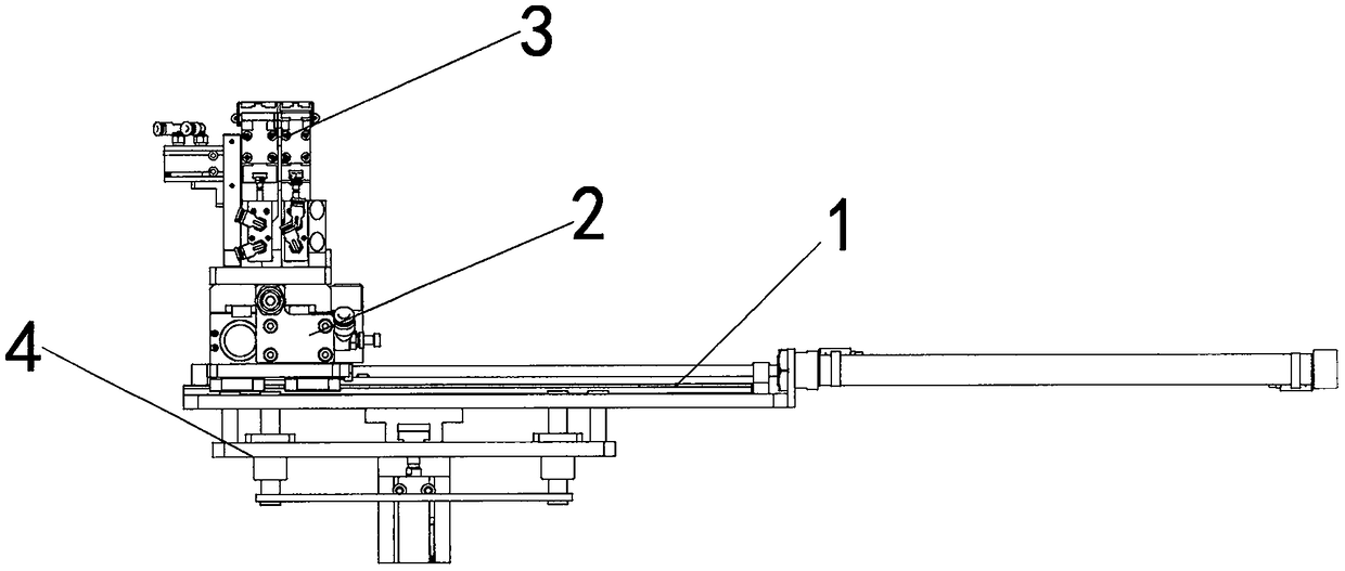
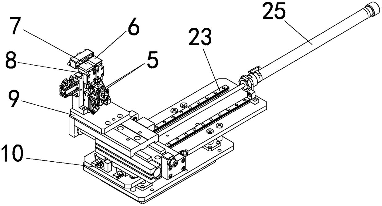
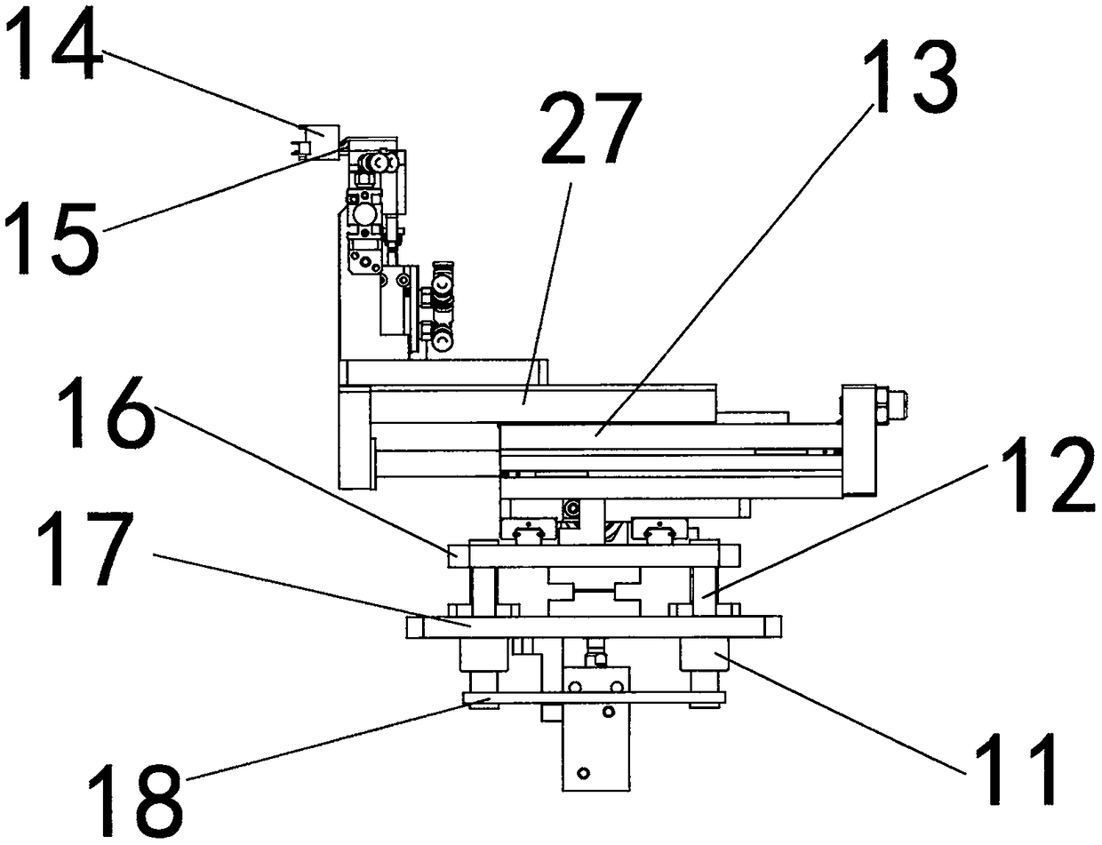
[0022] Combine below Figure 1-4 A detailed description of a PIN-separating needle insertion device of the present invention: a PIN-separated needle insertion device includes a transplanting mechanism 1 , a slide mechanism 2 , a clamping mechanism 3 and a lifting mechanism 4 . The lifting mechanism 4 is located at the bottom of the whole device. The top of the lifting mechanism 4 is provided with a transplanting mechanism 1 . A sliding table mechanism 2 is provided above the transplanting mechanism 1 . A clamping mechanism 3 is provided above the slide mechanism 2 . The lifting mechanism 1 includes a lifting mechanism fixed plate 17 and a lifting mechanism movable plate 18 . The bottom of the transplanting mechanism 1 is provide...


PUM


Abstract

The invention relates to a pin plugging device for separating pins, and the device comprises a transplanting mechanism, a sliding table mechanism, a clamping mechanism and a lifting mechanism. The lifting mechanism is disposed at the bottom of the whole device. The transplanting mechanism is disposed above the lifting mechanism, and the sliding table mechanism is disposed above the transplanting mechanism. The clamping mechanism is disposed above the sliding table mechanism. The device comprises the clamping mechanism which is used for the PIN separation of the pins on a PIN strip, and performs the staggered clamping of the PINs which are cut. The device is also provided with the transplanting mechanism, the sliding table mechanism and the lifting mechanism, and is provided with the clamping mechanism which can achieve the clamping and plugging of different PINs. The displacements in the three directions (X, Y and Z) are adjustable, so as to meet the plugging of pins at different spatial positions. The device is very practical for the plugging of pins at multiple PIN positions of the same type of products or a complex plastic part, can be suitable for different types of pin plugging machines, and represents the value and actual benefits.

Description

technical field [0001] The invention belongs to the technical field of plastic parts processing and molding equipment, and in particular relates to a pin insertion device for dividing PINs. Background technique [0002] For plastic parts that require pins, especially various electronic connectors, molding is usually achieved by assembling plastic parts and multiple metal PIN pins. The assembly method of the PIN pin and the plastic part is generally plug-in or injection molding. Sub-PIN insertion refers to inserting multiple different PIN pins or the same PIN pin into the preset hole of the plastic part. Injection molding refers to putting the PIN needle into the mold and directly injection molding to form a plastic part that is seamlessly fixed with the PIN needle. When the PIN needle is processed, the conductive metal material is usually first cut into a strip structure, and then a specific PIN needle structure is punched out with a punch. For the convenience of transpor...

Claims


Application Information

Patent Timeline
Patent Type & Authority Applications(China)
IPC IPC(8): H01R43/20
CPCH01R43/20
Inventor 周建国林贤董龚爱华
Owner 温州瑞孚自动化科技有限公司
Why Eureka
Try Eureka