Mounting base with moisture-proof function for low-voltage power distribution cabinet

A technology for installing bases and power distribution cabinets. It is used in substation/distribution device housing, substation/switchgear cooling/ventilation, electrical components, etc. The problem of moisture damage to the electric cabinet can improve the fixing effect, improve the stability, and improve the anti-moisture function.

Inactive Publication Date: 2019-02-01
十堰市神针工贸有限公司
View PDF0 Cites 1 Cited by
  • Summary
  • Abstract
  • Description
  • Claims
  • Application Information

AI Technical Summary

Problems solved by technology

[0003] At present, when the existing low-voltage power distribution cabinets are in direct contact with the ground, the damp cold air on the ground or the moisture in the air will directly penetrate into the low-voltage power distribution cabinets from the ground, causing moisture damage in the low-voltage power distribution cabinets, and seriously soaking the lines. and devices, causing the devices to burn out. The existing low-voltage power distribution cabinets will also be equipped with mounting bases. The mounting bases do not have a good moisture-proof function, which will also affect the normal operation of the power distribution cabinet. The installation effect of the cabinet is poor, resulting in poor stability

Method used


Image

  • Mounting base with moisture-proof function for low-voltage power distribution cabinet
  • Mounting base with moisture-proof function for low-voltage power distribution cabinet
  • Mounting base with moisture-proof function for low-voltage power distribution cabinet

Examples


Embodiment Construction

[0019] The following will clearly and completely describe the technical solutions in the embodiments of the present invention with reference to the accompanying drawings in the embodiments of the present invention. Obviously, the described embodiments are only some, not all, embodiments of the present invention.

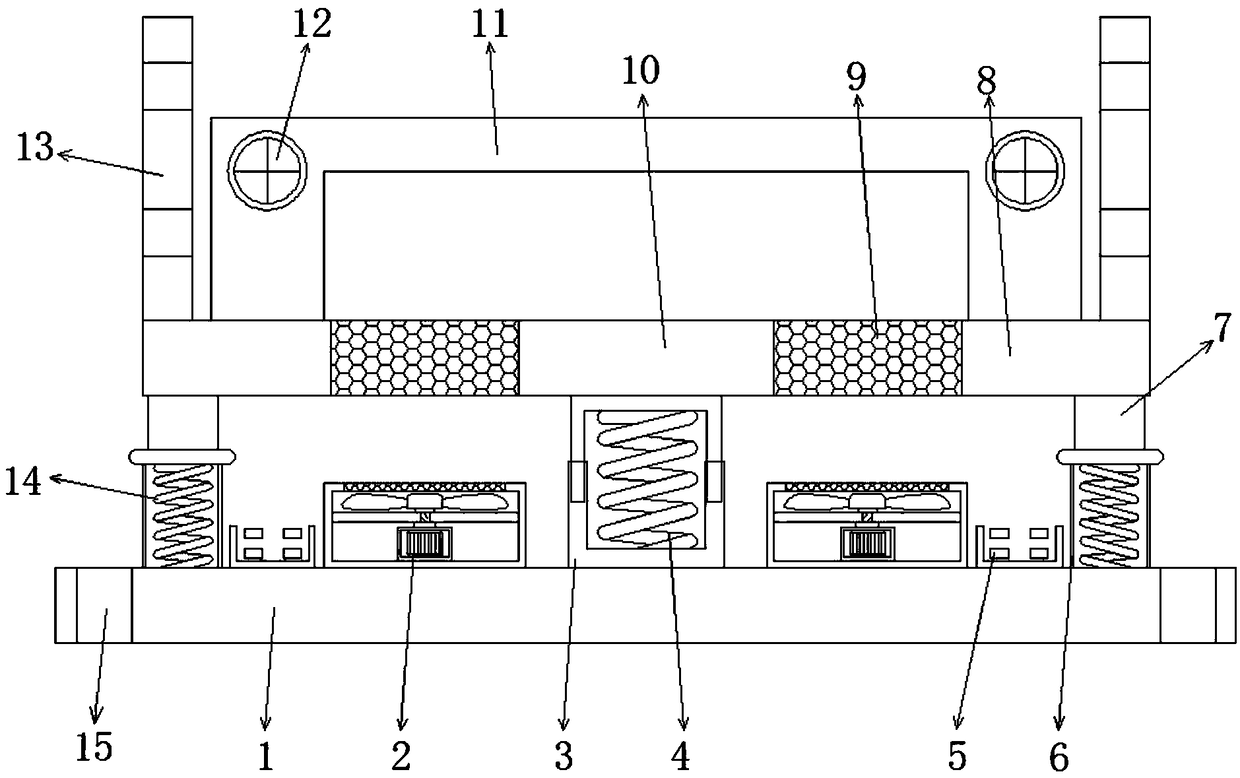
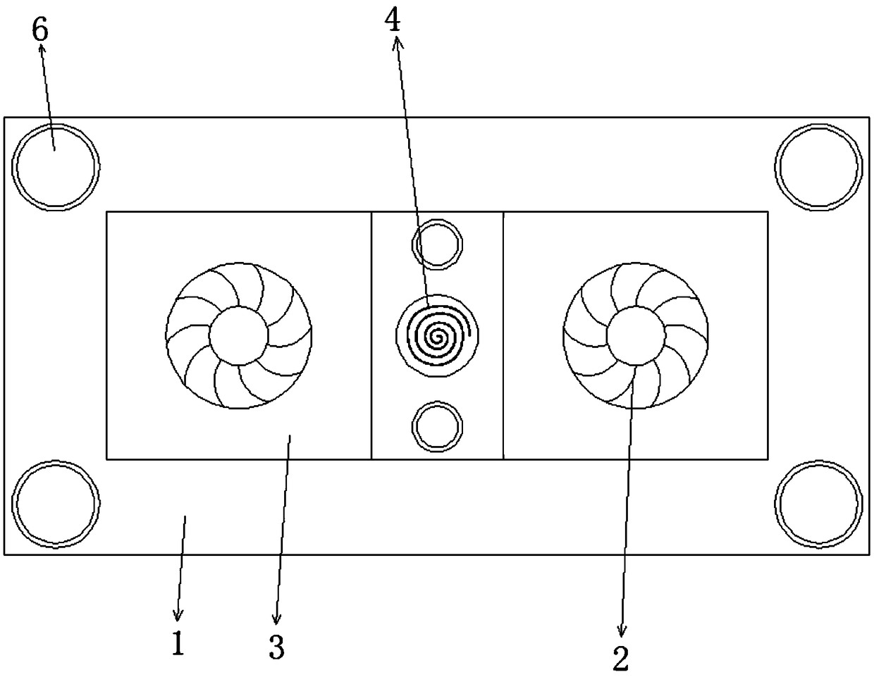
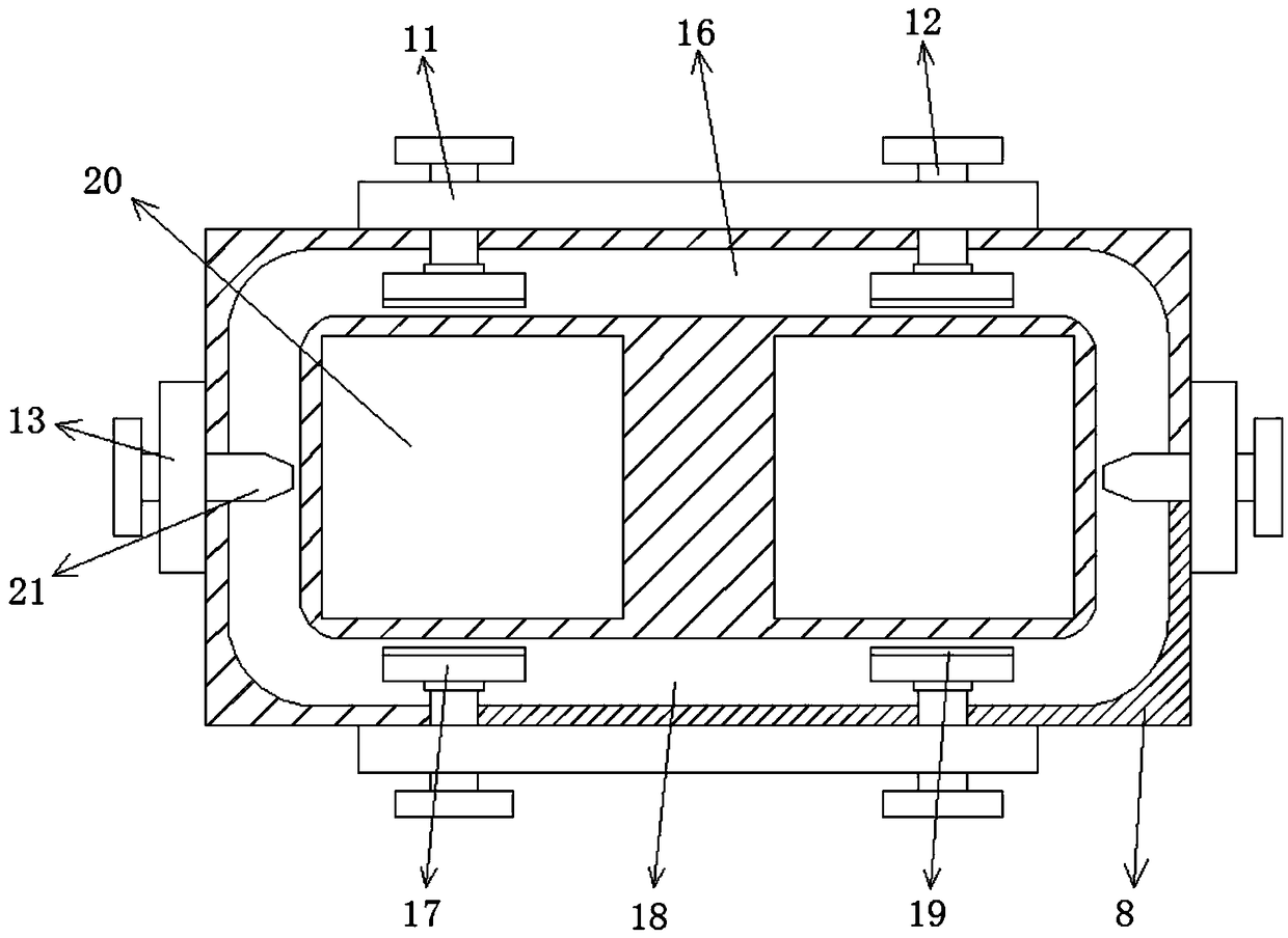
[0020] refer to Figure 1-3 , a low-voltage power distribution cabinet with a moisture-proof installation base, including an installation base plate 1, the two ends of the top of the installation base plate 1 are opened with installation holes 15, and the middle position of the top outer wall of the installation base plate 1 is welded with an installation tube 3, the installation Jacks are opened on the outer wall around the top of the cylinder 3, and the inner wall of the jack is plugged with a mounting post. The top inner wall of the mounting post and the bottom inner wall of the installation tube 3 are welded with the main spring 4, and the top outer wall of the mo...


PUM


Abstract

The invention discloses a mounting base with a moisture-proof function for a low-voltage power distribution cabinet. The mounting base comprises a mounting bottom plate; mounting holes are formed in the two ends of the top of the mounting bottom plate; a mounting cylinder is arranged at the middle part of the outer wall of the top of the mounting bottom plate; insertion holes are formed in the outer wall around the top of the mounting cylinder; mounting columns are arranged at the inner walls of the insertion holes; and main springs are arranged the inner walls of the tops of the mounting columns and the inner wall of the bottom of the mounting cylinder. A mounting top plate is arranged at the outer walls of the tops of the mounting columns. Buffer cylinders are arranged at the outer wallsof the two sides of the top of the mounting bottom plate; and buffer rods are arranged at the inner walls of the tops of the buffer cylinders. According to the invention, the contact of humid cold air with a low-voltage power distribution cabinet during the rising process is stopped; a micro fan is used for carrying out ventilation and removing the moisture at the bottom of the low-voltage powerdistribution cabinet, so that the anti-moisture function of the low-voltage power distribution cabinet is improved substantially; the mounting base plays a role in buffering and damping, so that the fixation effect of the low-voltage power distribution cabinet is improved.

Description

technical field [0001] The invention relates to the technical field of low-voltage power distribution cabinets, in particular to a moisture-proof installation base for low-voltage power distribution cabinets. Background technique [0002] The low-voltage power distribution cabinet is a combined assembly structure that integrates various line assemblies to control the normal operation of the entire factory workshop line. When the low-voltage power distribution cabinet is installed, it is generally placed on the ground and in contact with the ground. [0003] At present, when the existing low-voltage power distribution cabinets are in direct contact with the ground, the damp cold air on the ground or the moisture in the air will directly penetrate into the low-voltage power distribution cabinets from the ground, causing moisture damage in the low-voltage power distribution cabinets, and seriously soaking the lines. and devices, causing the devices to burn out. The existing low...

Claims


Application Information

Patent Timeline
Patent Type & Authority Applications(China)
IPC IPC(8): H02B1/56H02B1/54H02B1/50H02B1/28
CPCH02B1/565H02B1/28H02B1/50H02B1/54
Inventor 郝兴强吴远林赵天财解春娥郝兴德
Owner 十堰市神针工贸有限公司
Why Eureka
Try Eureka