
Debris flow sediment transport control method suitable for wide valley type debris flow valley

A control method and technology for debris flow, applied in water conservancy projects, marine engineering, coastline protection, etc., can solve the problems of lack of development and utilization of sediment resources, difficulty in achieving the expected goal of governance, reduction of reservoir capacity, etc., to improve governance effectiveness and efficiency. The effect of development, utilization and improvement of ecological landscape

Inactive Publication Date: 2016-06-01
INST OF MOUNTAIN HAZARDS & ENVIRONMENT CHINESE ACADEMY OF SCI
View PDF6 Cites 0 Cited by
  • Summary
  • Abstract
  • Description
  • Claims
  • Application Information

AI Technical Summary

Problems solved by technology

[0003] At present, civil engineering measures such as sand retaining dams, drainage channels, silting yards, and valley square groups are often used to solve the problem of sediment transport in valley-type debris flows. These engineering measures have played a positive role in the prevention and control of debris flows. The purpose of treatment is mainly to consider how to safely and smoothly transport a large amount of mud-rock flow sediment to the designated place or discharge it into the main river valley. Not only the engineering cost is high, but also the large amount of sediment entering the main river will easily cause the river bed to rise, the storage capacity of the reservoir will shrink, and even When a large-scale debris flow breaks out, it enters the main river through the drainage channel and submerges buildings along the river such as farmland, railways, highways, and hydropower facilities, making it difficult to achieve the expected goal of governance
In terms of treatment ideas, most of the existing treatment technical measures focus on sediment drainage, without considering how to use the favorable terrain conditions of valleys to rationally and optimally distribute a large amount of sediment, and lack of reasonable and effective development and utilization of sediment resources

Method used


Image

  • Debris flow sediment transport control method suitable for wide valley type debris flow valley
  • Debris flow sediment transport control method suitable for wide valley type debris flow valley
  • Debris flow sediment transport control method suitable for wide valley type debris flow valley

Examples


Embodiment 1

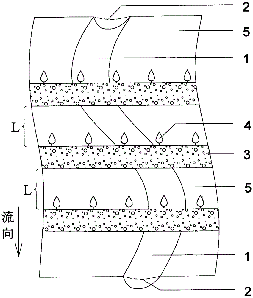
[0027] Such asfigure 1 , Figure 4 , Figure 5 shown. For a wide valley type debris flow valley with a longitudinal slope of 3-5 degrees and a transverse width of 50-200m, the debris flow control method of the present invention is used in the wide valley type valley.

[0028] In the debris flow flow area and accumulation area in the gully, the existing loose solid matter on the ditch bed is used to backfill the sand transport ditch 1 on the ditch bed. The trench bed surface 5 jointly forms a flat and wide trench bed surface. In the debris flow circulation area and accumulation area in the valley, use the existing loose solid materials on the ditch bed to build 15 sand-retaining earth walls 3 horizontally along the valley contour line and distributed at a certain interval; the specifications of each earth wall 3: The top width b1 of the earth wall 3 is 0.8m, the bottom width b2 of the earth wall 3 is 1.0m, the height h of the earth wall 3 is 0.6m, and the length of the earth...

Embodiment 2

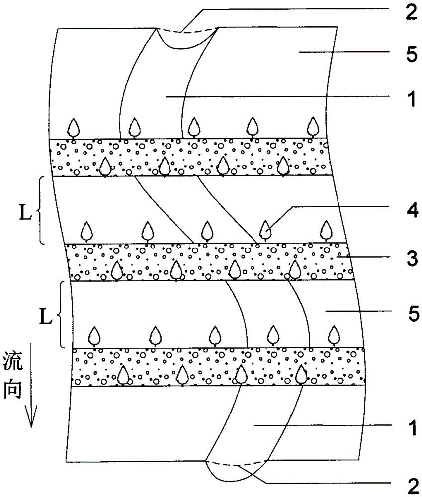
[0030] like figure 2 , Figure 4 , Figure 6 shown. For a wide valley type debris flow valley with a gully bed longitudinal slope of 6-8 degrees and a valley transverse width of 180-320m, the debris flow and sand transport control method of the present invention is used in the wide valley type valley.

[0031] In the debris flow flow area and accumulation area in the gully, the existing loose solid matter on the ditch bed is used to backfill the sand transport ditch 1 on the ditch bed. The trench bed surface 5 jointly forms a flat and wide trench bed surface. In the debris flow circulation area and accumulation area in the valley, use the existing loose solid materials on the ditch bed to build 12 sand-retaining earth walls 3 horizontally along the valley contour line and distributed at a certain interval; the specifications of each earth wall 3: The top width b1 of the earth wall 3 is 1.2m, the bottom width b2 of the earth wall 3 is 2.2m, the height h of the earth wall 3...

Embodiment 3

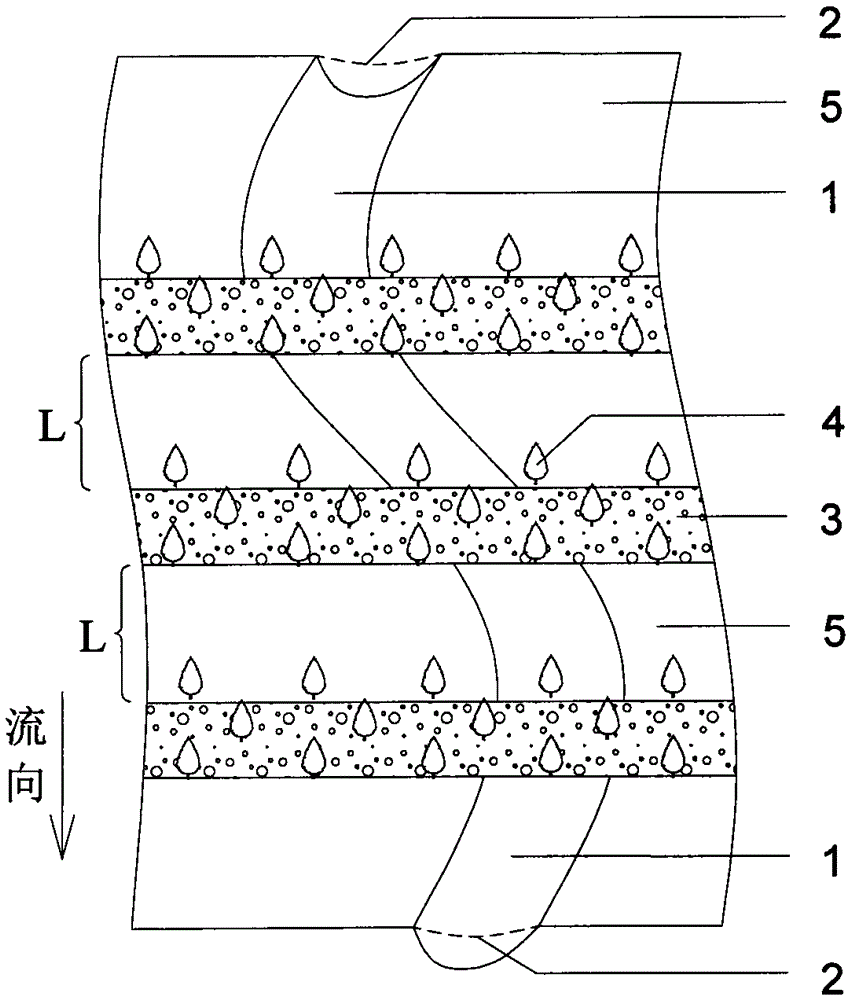
[0033] like image 3 , Figure 4 , Figure 7 shown. For a wide valley type debris flow valley with a gully bed longitudinal slope of 11-13 degrees and a valley transverse width of 220-360m, the debris flow and sand transport control method of the present invention is used in the wide valley type valley.

[0034] In the debris flow flow area and accumulation area in the valley, the existing loose solid matter on the ditch bed is used to backfill the sand transport ditch 1 on the ditch bed. The trench bed surface 5 jointly forms a flat and wide trench bed surface. In the debris flow circulation area and accumulation area in the valley, use the existing loose solid materials on the ditch bed to build 8 sand-retaining earth walls 3 distributed in a certain interval along the contour line of the valley; the specification of each earth wall 3: soil The top width b1 of the wall 3 is 1.5m, the bottom width b2 of the earth wall 3 is 2.6m, the height h of the earth wall 3 is 1.8m, a...


PUM


Abstract

The invention discloses a debris flow sediment transport control method suitable for a broad valley type debris flow gully. The transverse width of the broad valley type debris flow gully is 50-400 m, and the longitudinal gradient of a gully bed is smaller than or equal to 15 degrees; a sediment transport groove in the gully bed is backfilled by utilizing existing loose solid materials on the gully bed in the flowing area and accumulation area of debris flow in the gully, and the ground line curvature of the backfilled groove is smaller than three percents; multiple sand blocking cob walls distributed at a certain interval are transversely built by utilizing the existing loose solid materials on the gully along the gully contour line in the flowing area and accumulation area of the debris flow in the gully; deep-rootedness arbores or bamboos are planted at the edges of the cob walls along the trend of the cob walls in the shape of a strip. According to the method, not only is sediment effectively prevented from entering a main river, but also a large amount of the blocked sediment can be locally converted into precious land resources, and the comprehensive corporate governance goals of achieving low governance cost and high economic benefit, changing harm to benefit and improving the ecology landscape of the gully are achieved.

Description

technical field [0001] The invention relates to a method for controlling mud-rock flow and sand transport in valleys, in particular to a method for controlling mud-rock flow and sand transport in wide valley-type mud-rock flow valleys by changing the shape of the ditch bed in the circulation area and accumulation area. Background technique [0002] In recent years, with the in-depth development of China's western region, the development of cascade hydropower projects in the upper reaches of the Yangtze River and the construction of large-scale railway and highway projects have caused damage to unstable mountains in mountainous areas, and after the "5.12" Wenchuan Earthquake, a large number of non-debris flows The ditch turns into a low-frequency or high-frequency debris flow ditch, which increases the ability of the ditch to input sediment into the main river, resulting in increased river sediment, reduced reservoir capacity, and even blocking the river to form a barrier lake...

Claims


Application Information

Patent Timeline
Patent Type & Authority Patents(China)
IPC IPC(8): E02B3/00E02B8/02
Inventor 王道杰崔鹏常士秋陈晓清游勇葛永刚洪勇苏凤环
Owner INST OF MOUNTAIN HAZARDS & ENVIRONMENT CHINESE ACADEMY OF SCI
Learn More