
Lateral magnetic flux motor

A transverse flux motor, axial technology, applied in the direction of magnetic circuits, electric components, electrical components, etc., can solve the problems that restrict the promotion of transverse flux permanent magnet motor engineering, stator punching cannot be stacked, and the punching process is complicated , to achieve the effect of improving structural performance, reducing process complexity, and ensuring efficiency

Pending Publication Date: 2019-02-01
HUAIAN WELLING MOTOR MFG +1
View PDF5 Cites 17 Cited by
  • Summary
  • Abstract
  • Description
  • Claims
  • Application Information

AI Technical Summary

Problems solved by technology

[0003] Although the transverse flux motor has the characteristics of electromagnetic decoupling and high efficiency, its magnetic circuit structure prevents the stator laminations from being laminated in the axial direction to reduce eddy current loss. Whether the stator core is laminated tangentially or radially, There are problems such as complex punching process and difficult winding, which restrict the engineering promotion of transverse flux permanent magnet motor

Method used


Image

  • Lateral magnetic flux motor
  • Lateral magnetic flux motor
  • Lateral magnetic flux motor

Examples


Embodiment Construction

[0037] In order to understand the above-mentioned purpose, features and advantages of the present invention more clearly, the present invention will be further described in detail below in conjunction with the accompanying drawings and specific embodiments. It should be noted that, in the case of no conflict, the embodiments of the present application and the features in the embodiments can be combined with each other.

[0038] In the following description, many specific details are set forth in order to fully understand the present invention. However, the present invention can also be implemented in other ways different from those described here. Therefore, the protection scope of the present invention is not limited by the specific details disclosed below. EXAMPLE LIMITATIONS.

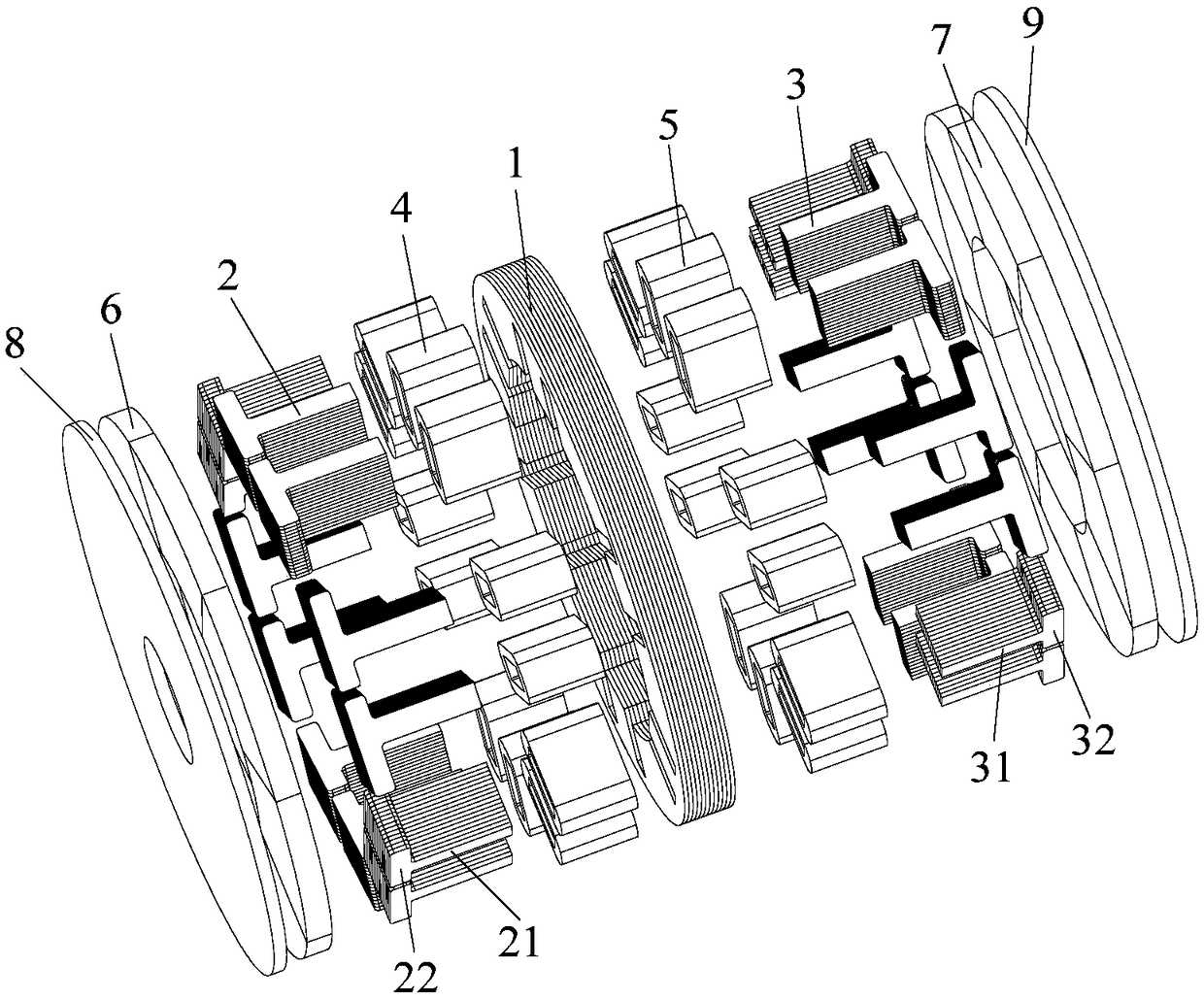
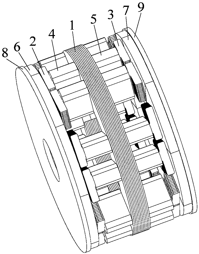
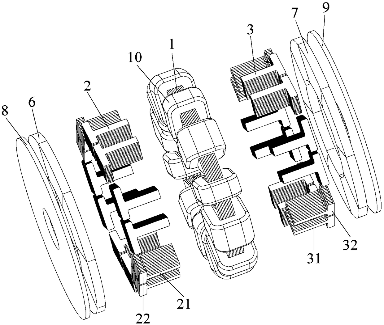
[0039] Refer below Figure 1 to Figure 7 A transverse flux machine according to some embodiments of the invention is described.

[0040] Such as Figure 1 to Figure 7 As shown, a transverse flux m...


PUM


Abstract

The invention provides a lateral magnetic flux motor, and the motor comprises a stator, a first rotor and a second rotor, wherein the stator comprises a stator yoke, a plurality of first stator teethand a plurality of second stator teeth. The stator yoke is formed by the axial stacking of a plurality of stator yoke punching sheets, and each of the first stator teeth and each of the second statorteeth are each composed of a plurality of identically-shaped stator tooth punching sheets which are stacked in a radial direction. The first stator teeth and the first stator teeth are fixed at two sides of the stator yoke in the axial direction. The first rotor and the second rotor are respectively disposed at two sides of the stator in the axial direction, and the first rotor includes a first back iron and a plurality of first permanent magnets that are magnetized in the axial direction. The second rotor includes a second back iron and a plurality of second permanent magnets that are magnetized in the axial direction. The first permanent magnet and the second permanent magnet are in mirror symmetry. The magnetic flux motor provided by the invention not only simplifies the production process, but also improves the power density of the motor; by designing a lateral magnetic circuit structure, the motor achieves the electrical and magnetic decoupling, and the groove area is no longer restricted by a magnetic load.

Description

technical field [0001] The present invention relates to the technical field of motors, in particular to a transverse flux motor. Background technique [0002] With the gradual improvement of environmental protection awareness, motor efficiency has received more and more attention. From the perspective of motor design, the iron loss of the motor is determined by the magnetic induction intensity, which is directly related to the stator tooth width; the copper loss of the motor is determined by the winding resistance, which is related to the slot width (area). For motors with traditional structures, the slot width and tooth width are two mutually restrictive variables. Under the premise of a fixed shape, it is impossible to optimize both simultaneously. However, the transverse flux motor is an orthogonal decoupling of the electric load and the magnetic load, and no longer There are constraints that can greatly improve motor efficiency. [0003] Although the transverse flux mo...

Claims


Application Information

Patent Timeline
Patent Type & Authority Applications(China)
IPC IPC(8): H02K16/04H02K16/02H02K1/27H02K1/14
CPCH02K1/146H02K1/2793H02K16/025H02K16/04
Inventor 李文瑞左亚军于明湖李虎周倩云
Owner HUAIAN WELLING MOTOR MFG
Learn More