Veneer toothing machine

A technology of tooth connection and veneer, applied in the field of veneer tooth connection machine, can solve the problems of low work efficiency, large heat generation of the motor, inability to achieve high-speed operation, etc., and achieve the effect of saving labor costs

Pending Publication Date: 2019-02-05
GUANGZHOU HENGWEI ELECTROMECHANICAL EQUIP CO LTD
View PDF0 Cites 9 Cited by
  • Summary
  • Abstract
  • Description
  • Claims
  • Application Information

AI Technical Summary

Problems solved by technology

In the actual use process, the feeding device of the above-mentioned plank splicing machine has the following defects: because the planks are conveyed intermittently and frequently for many times, and the feeding device uses a motor, the motor starts and stops frequently intermittently, resultin

Method used


Image

  • Veneer toothing machine
  • Veneer toothing machine
  • Veneer toothing machine

Examples


Example Embodiment

[0043] Below in conjunction with accompanying drawing, invention is described in further detail.

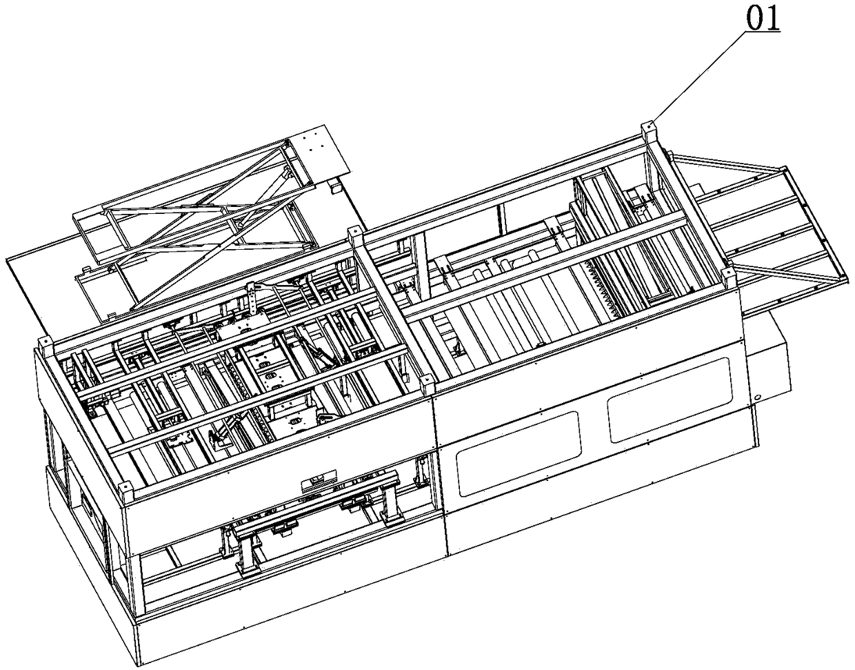
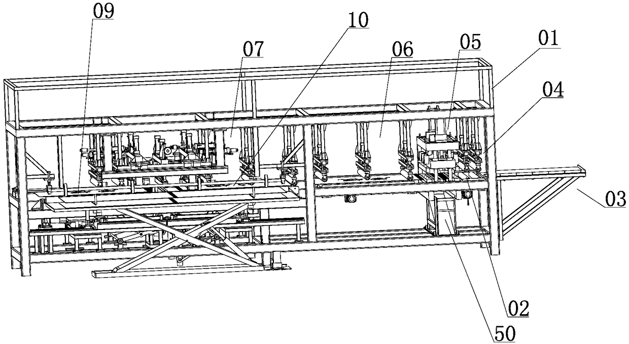
[0044] like Figure 1-12As shown in the figure, a single-plate toothed machine includes a frame 01, a roller conveyor belt 02 provided on the frame 01, a feeding table 03 provided at one end of the roller conveyor belt 02, and a roller conveyor belt 02. Above 02 are sequentially provided a feeding rolling conveying device 04, a plate tooth cutting device 05, a buffer rolling conveying device 06 and a panel assembling device 07 that cooperate with the roller conveyor belt 02 to convey the plate; Some lower bottom plate 51 and upper bottom plate 52, between the lower bottom plate 51 and the upper bottom plate 52 are provided with upright columns 53 supporting the lower bottom plate 51 and the upper bottom plate 52, and between the lower bottom plate 51 and the upper bottom plate 52 are provided with up and down along the column 53. The splint 54 is provided with two rows of the fi...


PUM


Abstract

The invention discloses a veneer toothing machine. The veneer toothing machine comprises a rack, a roller conveying belt, a feeding table, a feed rolling and conveying device, a plate tooth cutting device, a buffer rolling and conveying device and a plate splicing device, wherein the roller conveying belt is arranged on the rack, the feeding table is arranged on one end of the roller conveying belt, and the feed rolling and conveying device, the plate tooth cutting device, the buffer rolling and conveying device and the plate splicing device are arranged above the roller conveying belt in sequence and are matched with the roller conveying belt to convey plates. The veneer toothing machine has the effects that the labor cost is reduced, and the automatic production is continuous.

Description

technical field [0001] The invention belongs to the field of wood processing equipment, in particular to a veneer gear splice machine capable of splicing plates. Background technique [0002] China's wood processing technology has been handed down for a long time. Ancient furniture making, wood carving and tool making are all inseparable from wood processing. In the past, carpenters used tools such as bangs, planes, saws, chisels, and axes for processing. Round tenon and square tenon are processed to connect the boards. Such tools and methods are obviously not suitable for modern wood production. In modern wood production, most of the obtained wood is long strips. If it is necessary to process parts such as countertops, desktops and cabinets, it is necessary to connect the strip-shaped sheets horizontally. The way of lateral connection is usually to use glue for bonding to form a square board surface. In the prior art, when performing the bonding process, it is usually ...

Claims


Application Information

Patent Timeline
IPC IPC(8): B27D1/10B27D5/00B27G11/00B27F1/00
CPCB27D1/10B27D5/00B27F1/00B27G11/00
Inventor 汪爱明
Owner GUANGZHOU HENGWEI ELECTROMECHANICAL EQUIP CO LTD
Why Eureka
Try Eureka