Ejection guide mechanism of plastic mould

A technology of plastic molds and guiding mechanisms, which is applied in the field of plastic molds, can solve problems such as poor stability, and achieve high stability and strong practicability

Inactive Publication Date: 2019-02-05
HUANGSHI SANMU PLASTIC MOLD
View PDF0 Cites 2 Cited by
  • Summary
  • Abstract
  • Description
  • Claims
  • Application Information

AI Technical Summary

Problems solved by technology

[0003] The purpose of the present invention is to solve the disadvantages of poor stability when exporting in the prior art, and propose a ejection guide mechanism for plastic molds

Method used


Image

  • Ejection guide mechanism of plastic mould
  • Ejection guide mechanism of plastic mould

Examples


Embodiment Construction

[0014] The following will clearly and completely describe the technical solutions in the embodiments of the present invention with reference to the accompanying drawings in the embodiments of the present invention. Obviously, the described embodiments are only some, not all, embodiments of the present invention.

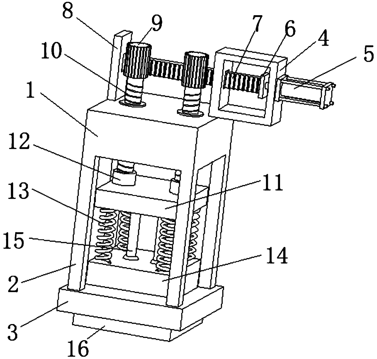
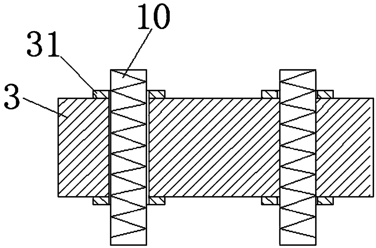
[0015] refer to Figure 1-2 , an ejection guide mechanism of a plastic mold, comprising a movable mold base 1, a plurality of support rods 2 are arranged on the movable mold base 1, and the support rods 2 are fixedly connected with the movable mold base 1, and the support rods 2 are far away from the movable mold base 1 One end is provided with a support plate 3, and the support rods 2 are all fixedly connected with the support plate 3, and one end of the bottom of the movable mold base 1 is provided with a fixed frame 4, and the fixed frame 4 is fixedly connected with the movable mold base 1, and the fixed frame 4 is provided with an electric motor. The cylinder 5 a...


PUM


Abstract

The invention relates to the technical field of plastic moulds, in particular to an ejection guide mechanism of a plastic mould. The ejection guide mechanism comprises a movable mould base. Supportingrods are arranged on the movable mould base. A supporting plate is arranged at one ends of the supporting rods. A fixing frame is arranged at the bottom of the movable mould base. An electric cylinder is arranged on the fixing frame. A connecting block is arranged in the fixing frame. A sliding rack is arranged on one side of the connecting block. A guide plate is arranged at one end of the bottom of the movable mould base. Two symmetric gears are arranged on one side of the sliding rack. Lead screws are arranged at the tops of the gears correspondingly. Threaded sleeves are arranged in the movable mould base. A sliding support seat is arranged on the upper portions of the lead screws. Clamp sleeves are arranged at the bottom of the sliding support seat. Buffer springs are arranged at thetop of the sliding support seat. A fixing support seat is arranged at one ends of the buffer springs. Push rods are arranged at the top of the sliding support seat. A molding core is fixedly connected into the supporting plate. The ejection guide mechanism is high in practicability and deserves to be popularized.

Description

technical field [0001] The invention relates to the technical field of plastic molds, in particular to an ejection guide mechanism for plastic molds. Background technique [0002] Plastic mold is a combined plastic mold used for compression molding, extrusion molding, injection molding, blow molding and low foaming molding. The die with variable cavity is a punch with a variable core composed of a punch combination base plate, a punch assembly, a punch combination clamp, a cavity cut-off component and a side section combination plate, the mold convex, concave mold and auxiliary The coordinated change of the molding system can process a series of plastic parts of different shapes and sizes. In the plastics processing industry, it is matched with plastic molding machines to give plastic products a complete configuration and precise dimensions. Due to the variety of plastics and processing methods, plastics The structures of molding machines and plastic products are complicate...

Claims


Application Information

Patent Timeline
Patent Type & Authority Applications(China)
IPC IPC(8): B29C45/40
CPCB29C45/4005
Inventor 罗威曾令才陶丹
Owner HUANGSHI SANMU PLASTIC MOLD
Why Eureka
Try Eureka