Electric drive hydraulic device for automobile braking system

An automobile brake system and electric drive technology, which is applied in the direction of brake transmission, brakes, vehicle components, etc., can solve the problems of reduced motor power and shortened emergency braking pressure build-up time, etc., to achieve motor power reduction and shortened build-up voltage Time, the effect of ensuring safety

Pending Publication Date: 2019-02-05
WUHU BETHEL ELECTRONICS CONTROL SYST
View PDF1 Cites 4 Cited by
  • Summary
  • Abstract
  • Description
  • Claims
  • Application Information

AI Technical Summary

Problems solved by technology

[0003] The purpose of the present invention is to provide an electric drive hydraulic device for automobile braking system, which uses oil pressure accumulator, accumulator solenoid valve, booster cylinder solenoid valve and motor drive booster cylinder to form a set of electric drive hydraulic pressure The device, through the control of the two pressure output sources of the oil pressure accumulator and the motor-driven booster cylinder, shortens the pressure building time during emergency braking, or the motor power required for the same pressure building time is reduced; The ABS action on the road will consume the supercharged cylinder oil, and the ABS function of the electronically controlled braking system will be interrupted when the supercharged cylinder is replenished. Intermittent, which solves the problem that the ABS function is interrupted when the fluid is replenished due to the consumption of the brake fluid in the pressurized cylinder during wheel-end braking

Method used


Image

  • Electric drive hydraulic device for automobile braking system
  • Electric drive hydraulic device for automobile braking system

Examples


Embodiment Construction

[0015] In order to deepen the understanding of the present invention, the present invention will be further described below in conjunction with examples, which are only used to explain the present invention and do not constitute a limitation to the protection scope of the present invention.

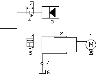
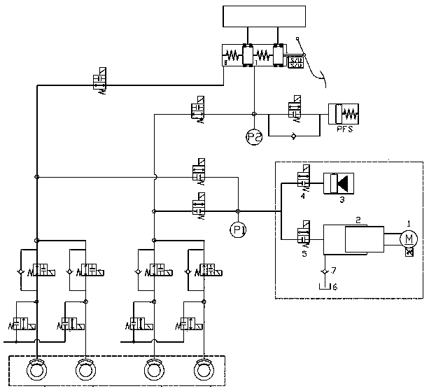
[0016] Such as figure 1 , 2 As shown, this embodiment provides an electric-driven hydraulic device for an automobile braking system, including a motor 1, a pressurized cylinder 2 and an oil pressure accumulator 3, and the outlet of the oil pressure accumulator 3 is provided with an accumulator The accumulator solenoid valve 4 controls the hydraulic accumulator 3 to supply oil to the braking system through the accumulator solenoid valve 4, the motor 1 is connected with the booster cylinder 2 through a transmission mechanism, and the outlet of the booster cylinder 2 is connected with The booster cylinder solenoid valve 5 controls the booster cylinder 2 to supply liquid through the booster ...


PUM


Abstract

The invention provides an electric drive hydraulic device for an automobile braking system. The electric drive hydraulic device for the automobile braking system comprises a motor, a pressure cylinderand an oil pressure accumulator, wherein an accumulator electromagnetic valve is arranged at an outlet of the oil pressure accumulator; the oil pressure accumulator is controlled to supply oil to thebraking system through the accumulator electromagnetic valve; the motor is connected with the pressure cylinder through a transmission mechanism; an outlet of the pressure cylinder is connected witha pressure cylinder electromagnetic valve; the pressure cylinder is controlled to supply liquid by the pressure cylinder electromagnetic valve; and the motor drives the pressure cylinder to output hydraulic pressure to charge the accumulator. Through the control of two pressure output sources of the oil pressure accumulator and the motor-driven pressure cylinder, the voltage buildup time during emergency braking is shortened. The ABS action on the low-attachment road surface can consume the oil of the pressure cylinder, and the ABS function of the electric control braking system can be interrupted when the pressure cylinder is refilled. However, the intervention of the oil pressure accumulator can realize that the function can be interrupted during the ABS action on the low-attachment roadsurface, so that the safety during driving is ensured.

Description

technical field [0001] The invention relates to the field of vehicle braking, in particular to an electric drive hydraulic device used in a vehicle braking system. Background technique [0002] With the gradual development of electronically controlled braking systems, the direction of technology research and development has developed to the wire controlled hydraulic braking system. Judging from the published patents, the current configuration scheme of the wire-controlled hydraulic brake system includes 14 solenoid valves and a motor-driven booster cylinder device for boosting, as shown in the patent application number US20170320477A1. But the wire-controlled hydraulic braking system includes a motor-driven booster cylinder, which completely relies on the ability of the motor for rapid boosting. In addition, when the wheel-end brakes are doing ABS (anti-lock braking system function) , the wheel end brake will continue to consume the brake fluid of the booster cylinder, so t...

Claims


Application Information

Patent Timeline
IPC IPC(8): B60T13/74B60T8/36
CPCB60T8/363B60T13/745
Inventor 袁永彬徐文泉
Owner WUHU BETHEL ELECTRONICS CONTROL SYST
Why Eureka
Try Eureka