
Unmanned aerial vehicle rotor arm structure with outer surface additionally provided with segmented constrained damping layer

A technology of restraining damping and outer surface, applied in the field of machinery, can solve the problems of reducing the robustness of the system, increasing the economic cost of the whole machine structure, affecting the endurance capacity, the flight stability of the load-bearing capacity, etc. Vibration effect, simple structure effect

Inactive Publication Date: 2019-02-05
NORTHEASTERN UNIV
View PDF5 Cites 1 Cited by
  • Summary
  • Abstract
  • Description
  • Claims
  • Application Information

AI Technical Summary

Problems solved by technology

Although the passive vibration absorber can produce significant effects at the natural frequency, the addition of a relatively large-mass vibration absorber to the drone will seriously affect its endurance, load-bearing capacity, and flight stability; represented by piezoelectric ceramics The active vibration suppression method has greater flexibility and has a good vibration suppression effect on the low frequency band of vibration, but its control system needs to provide an additional energy supply device, which not only increases the economic cost of the whole machine structure, but also reduces The robustness of the system, so it has great limitations in the application of vibration suppression of UAV rotor arm

Method used


Image

  • Unmanned aerial vehicle rotor arm structure with outer surface additionally provided with segmented constrained damping layer
  • Unmanned aerial vehicle rotor arm structure with outer surface additionally provided with segmented constrained damping layer
  • Unmanned aerial vehicle rotor arm structure with outer surface additionally provided with segmented constrained damping layer

Examples


Embodiment Construction

[0024] Below, the present invention will be described in further detail in combination with the accompanying drawings and specific embodiments.

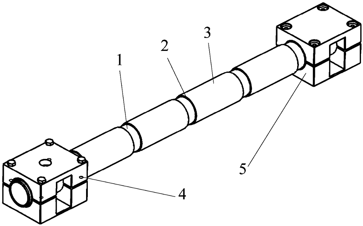
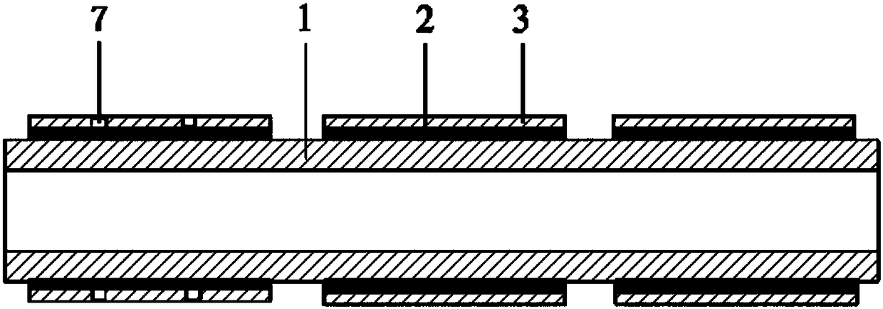
[0025] Such as Figure 1-2 As shown, the UAV rotor arm involved in the present invention adopts a segmented constrained damping layer, which includes a rotor arm body, a segmented constrained damping layer and a viscoelastic damping layer. The specific structure is as follows:

[0026] The rotor arm body 1 is a hollow cylindrical structure, and its material is carbon fiber; the viscoelastic damping layer 2 is a segmented hollow cylindrical shell structure, and its inner diameter is the same as the outer diameter of the rotor arm 1, and the outer diameter is the same as the inner diameter of the constrained damping layer 3, and its material is made of ZN-1 damping rubber; the constrained damping layer 3 is a segmented hollow cylindrical shell structure, the inner diameter of which is the same as the outer diameter of the viscoelastic ...


PUM


Abstract

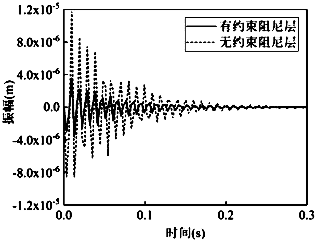
The invention provides an unmanned aerial vehicle rotor arm structure with the outer surface additionally provided with a segmented constrained damping layer. An unmanned aerial vehicle rotor arm comprises a rotor arm body, the constrained damping layer and a viscoelastic damping layer; the rotor arm body is of a hollow cylindrical structure made of a carbon fiber material; the constrained dampinglayer and the viscoelastic damping layer are each of a segmented hollow cylindrical shell structure, and are made of an aluminum alloy and ZN-1 damping rubber correspondingly; and the rotor arm, theviscoelastic damping layer and the constrained damping layer are tightly bonded in sequence from inside to outside. By additionally arranging the segmented constrained damping layer on the outer surface of the unmanned aerial vehicle rotor arm, the viscoelastic damping layer deforms through elastic bending vibration of the rotor arm, and thus vibration energy of the unmanned aerial vehicle rotor arm is dissipated rapidly for vibration reduction. The structure is simple, a main body structure of an unmanned aerial vehicle is not affected, extra additional mass and control device are not needed,the flight stability of the unmanned aerial vehicle is improved, and the vibration suppression effect in practical application is remarkable.

Description

technical field [0001] The invention relates to the mechanical field, in particular to a shock absorbing structure, and more specifically to a rotor arm vibration control structure of a multi-rotor drone. Background technique [0002] At present, UAVs have been widely used in high-altitude shooting, logistics, and farm work. In particular, the rapid development of the oil-driven multi-rotor UAV in recent years has further promoted its application due to its continuous improvement in carrying capacity, but the large load-bearing weight aggravates the vibration problem of the whole machine structure, which not only affects the The flight stability of the UAV is also very easy to cause damage to the structure of the UAV. [0003] In recent years, a large number of related studies have shown that the structural vibration of UAVs mainly comes from the resonance of the rotor arm, and the vibration mode is mainly in the bending mode. Traditional vibration suppression methods usua...

Claims


Application Information

Patent Timeline
Patent Type & Authority Applications(China)
IPC IPC(8): B64C27/00B64C27/32
CPCB64C27/001B64C27/32
Inventor 姚红良张钦李秋枫张世佳丁志雨闻邦椿
Owner NORTHEASTERN UNIV
Learn More