Method and system for deiciing of air foil wings of composite material

A composite material, rotor technology, used in deicing devices, transportation and packaging, final product manufacturing, etc., can solve problems such as being unsuitable for large windmills

Inactive Publication Date: 2002-10-23
LM GLASSFIBER
View PDF3 Cites 1 Cited by
  • Summary
  • Abstract
  • Description
  • Claims
  • Application Information

AI Technical Summary

Problems solved by technology

But this scheme is not suitable for large windmills,

Method used


Image

  • Method and system for deiciing of air foil wings of composite material
  • Method and system for deiciing of air foil wings of composite material
  • Method and system for deiciing of air foil wings of composite material

Examples


Embodiment Construction

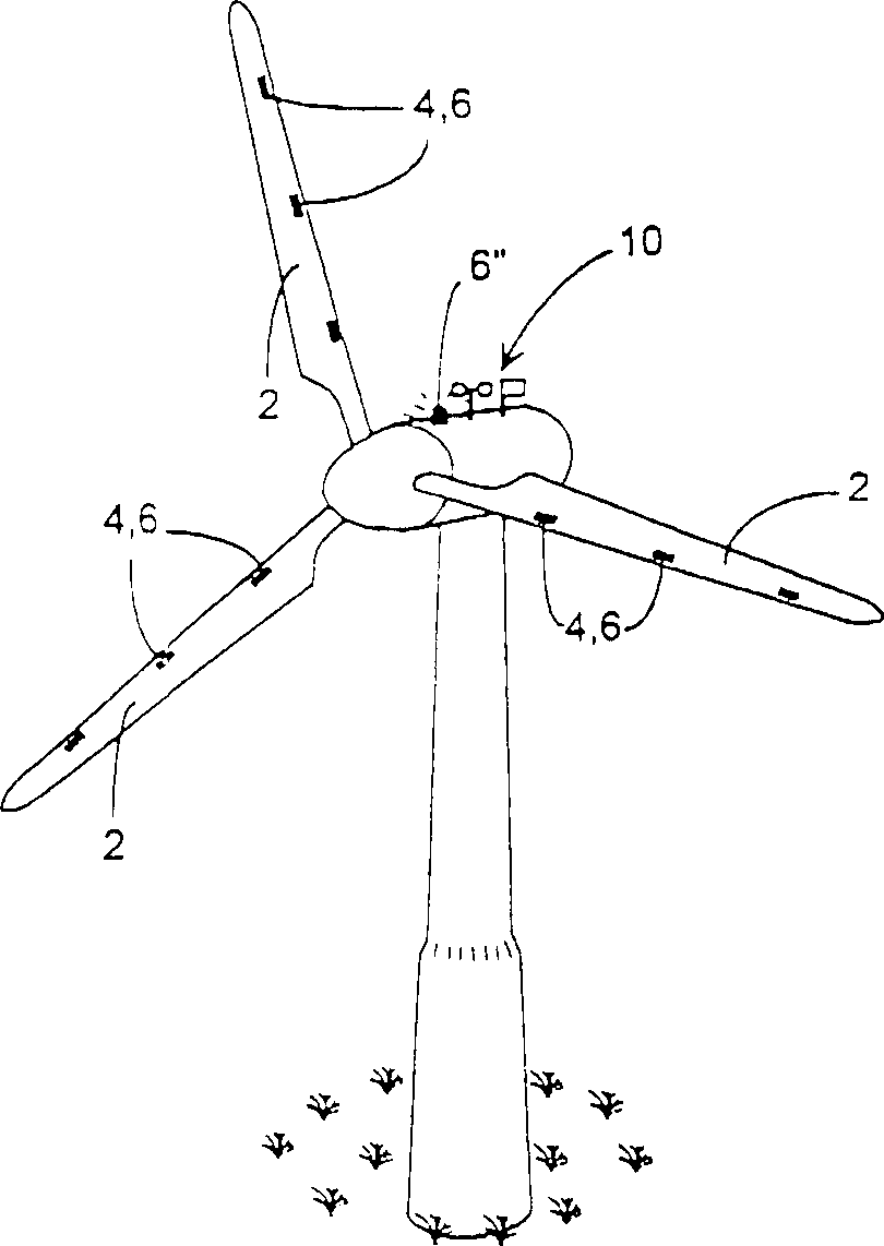
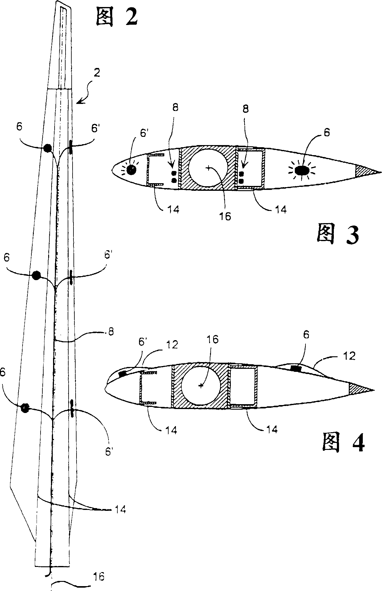
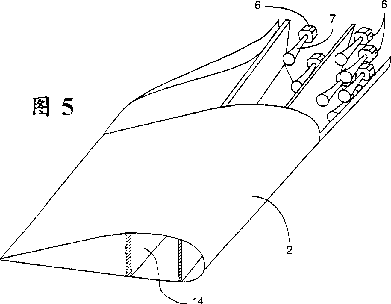
[0021] figure 1 A windmill is shown with a microwave heating system installed in it. The microwave equipment includes a plurality of microwave generators 6 installed on or in the rotor 2. In a preferred embodiment, a plurality of generators can be arranged in the rotor (as shown in FIGS. 2 and 3). Microwave generators 6' are preferably located along the leading edge of the rotor 2 in order to heat the leading edge area intensively. Certainly, the microwave generator 6 can also be arranged at other places on the rotor 2, as shown in Fig. 2, 3, 4.

[0022] When multiple microwave generators are mounted on the rotor, the rotor can be heated in sections. Optionally, the system can also be arranged so that each segment includes one or more generators 6, combined by a control system with humidity and temperature probes (not shown) also located on the rotor, so that only those segments that are icy are heated . A differential, demand-controlled heating of the rotor surface sectio...


PUM


Abstract

For avoiding icing of windmill wings of composite materials, use is made of microwave energy for heating of the composite material itself, this energy preferably being supplied from interior, fixedly mounted microwave generators in response to detection of potential climatic conditions for icing to occur. The wing surface can be coated with a layer reflecting the microwaves, whereby these may propagate by reflections through and between the shell parts of which the wing will normally consist. It is possible to arrange for selective heating by the use of more generators, which may then, each, be of the type that is already in production with modest size and at low costs for use in ordinary microwave ovens.

Description

technical field [0001] The present invention relates to a method of deicing a rotor, in particular a winged rotor such as a windmill rotor, and a corresponding system. Background technique [0002] For windmills in many parts of the world, it is known that the rotor blades of the windmill will freeze, reducing the effectiveness of the windmill drastically due to a corresponding change in the shape of the airfoil. Especially where the conditions for icing are suitable, ie low temperatures, high humidity or direct rain, ice formation on the rotors of windmills is a big problem. In some areas, the number of days with these conditions can be as high as 100 days per year. [0003] There are similar problems in aviation. Especially when the rotor is in motion, ice will form mainly on the leading edge of the rotor. This problem can be serious because the leading edge of the airfoil rotor greatly affects the aerodynamic characteristics of the rotor. Therefore, the efficiency of ...

Claims


Application Information

Patent Timeline
IPC IPC(8): B64D15/12F03D80/40
CPCB64D15/12H05B6/80H05B2214/02F03D80/40Y02E10/72Y02P70/50
Inventor 彼得·格雷博
Owner LM GLASSFIBER
Why Eureka
Try Eureka