Plant straw particle combustion machine

A plant straw and burner technology, which is applied to combustion equipment, solid fuel combustion, lighting and heating equipment, etc., can solve problems such as inability to use plant straws

Inactive Publication Date: 2019-02-05
柏家乐
View PDF6 Cites 5 Cited by
  • Summary
  • Abstract
  • Description
  • Claims
  • Application Information

AI Technical Summary

Problems solved by technology

[0004] The purpose of the present invention is to provide a plant straw particle burner to alleviate the technical problem in the prior art that plant straw cannot be used as fuel

Method used


Image

  • Plant straw particle combustion machine
  • Plant straw particle combustion machine
  • Plant straw particle combustion machine

Examples


Embodiment Construction

[0044] The technical solutions of the present invention will be clearly and completely described below in conjunction with the accompanying drawings. Apparently, the described embodiments are some of the embodiments of the present invention, but not all of them. Based on the embodiments of the present invention, all other embodiments obtained by persons of ordinary skill in the art without making creative efforts belong to the protection scope of the present invention.

[0045] In the description of the present invention, it should be noted that the terms "center", "upper", "lower", "left", "right", "vertical", "horizontal", "inner", "outer" etc. The indicated orientation or positional relationship is based on the orientation or positional relationship shown in the drawings, and is only for the convenience of describing the present invention and simplifying the description, rather than indicating or implying that the referred device or element must have a specific orientation, ...


PUM


Abstract

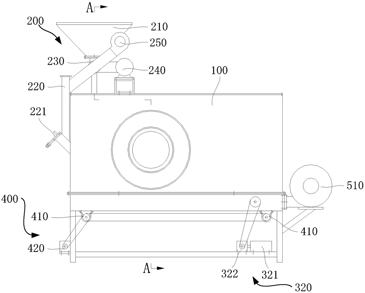
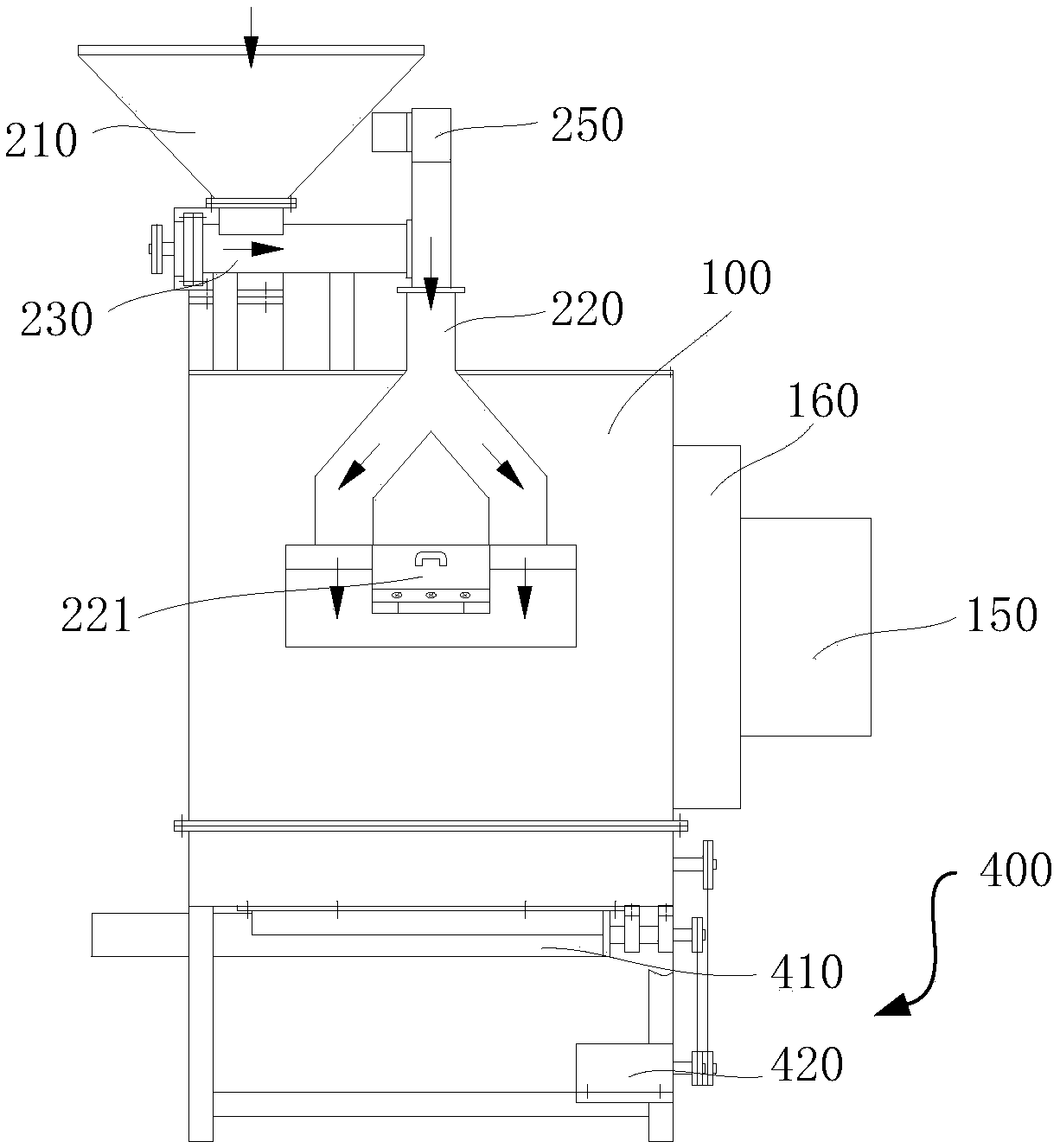
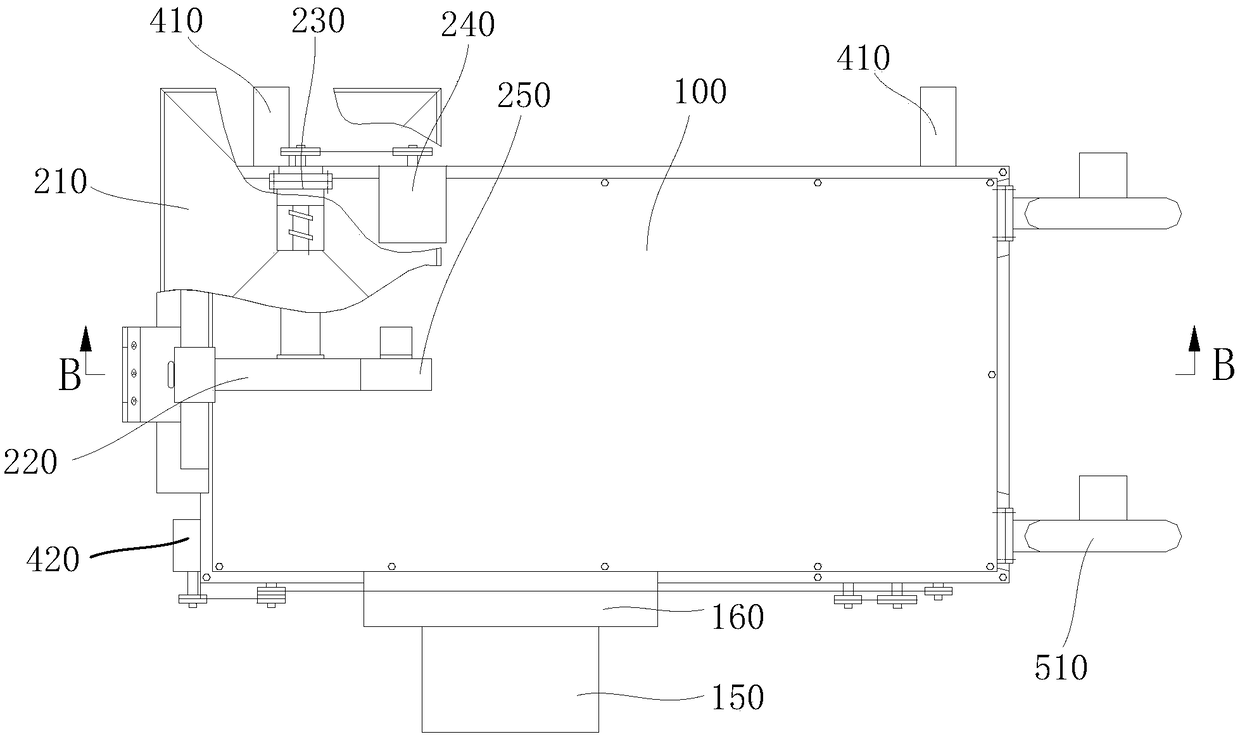
The invention discloses a plant straw particle combustion machine and relates to the technical field of combustion equipment. The technical problem that in the prior art, plant straw cannot be used asfuel is solved. The plant straw particle combustion machine comprises a combustion furnace body, a feeding device, a fire grate device and an ash discharging device. A hearth is formed in the combustion furnace body, and a flame spraying opening communicating with the hearth is formed in the side wall. The feeding device is installed at the outer portion of the combustion furnace body, and one end of the feeding device communicates with the hearth. The fire grate device is installed in the hearth and located below the outlet end of the feeding device and can bear plant straw particles to movein the direction away from the outlet end of the feeding device. The ash discharging device is installed below the combustion furnace body, communicates with the hearth and is used for discharging carbon ash in the hearth. The ash discharging device below the furnace body of the plant straw particle combustion machine can be used for discharging the carbon ash in the hearth in time, the phenomenon that the hearth is blocked by the carbon ash is avoided, and plant straw with much carbon ash can be used as fuel through the plant straw particle combustion machine.

Description

technical field [0001] The invention relates to the technical field of combustion equipment, in particular to a plant straw particle burner. Background technique [0002] Existing biomass pellet burners cannot use straw, corn stalks, etc. as fuel because these plant stalks have a lot of carbon ash after burning, and if they cannot be discharged out of the furnace, the furnace will be blocked and cannot be used. Existing biomass pellet burners can only use pellets made of wood chips and waste engineering boards as fuel. These fuels contain glue and gravel, which will pollute the environment when burned and damage boilers and the like. [0003] The information disclosed in this background section is only intended to enhance the understanding of the general background of the present invention, and should not be considered as an acknowledgment or any form of suggestion that the information constitutes the prior art that is known to those skilled in the art. Contents of the in...

Claims


Application Information

Patent Timeline
Patent Type & Authority Applications(China)
IPC IPC(8): F23B40/00F23J1/06
CPCF23B40/00F23J1/06
Inventor 柏家乐
Owner 柏家乐
Why Eureka
Try Eureka