Biomass fuel particle combustion equipment

A biomass fuel and combustion equipment technology, applied in the energy field, can solve the problems of increasing combustion efficiency, reducing work efficiency, and single function, and achieve the effects of increasing heating efficiency, increasing efficiency, and improving combustion efficiency

Inactive Publication Date: 2021-06-18
上海旖琥环境工程技术发展有限公司
View PDF7 Cites 0 Cited by
  • Summary
  • Abstract
  • Description
  • Claims
  • Application Information

AI Technical Summary

Problems solved by technology

[0004] The above scheme has a relatively simple structure and a single function, and cannot automatically fill in fuel.

Method used


Image

  • Biomass fuel particle combustion equipment
  • Biomass fuel particle combustion equipment
  • Biomass fuel particle combustion equipment

Examples


Embodiment Construction

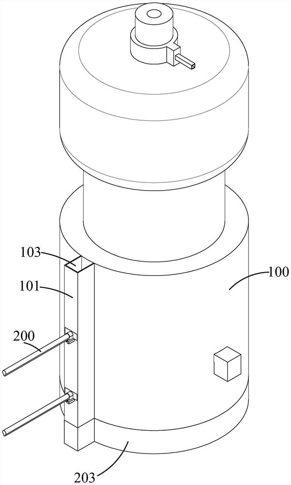
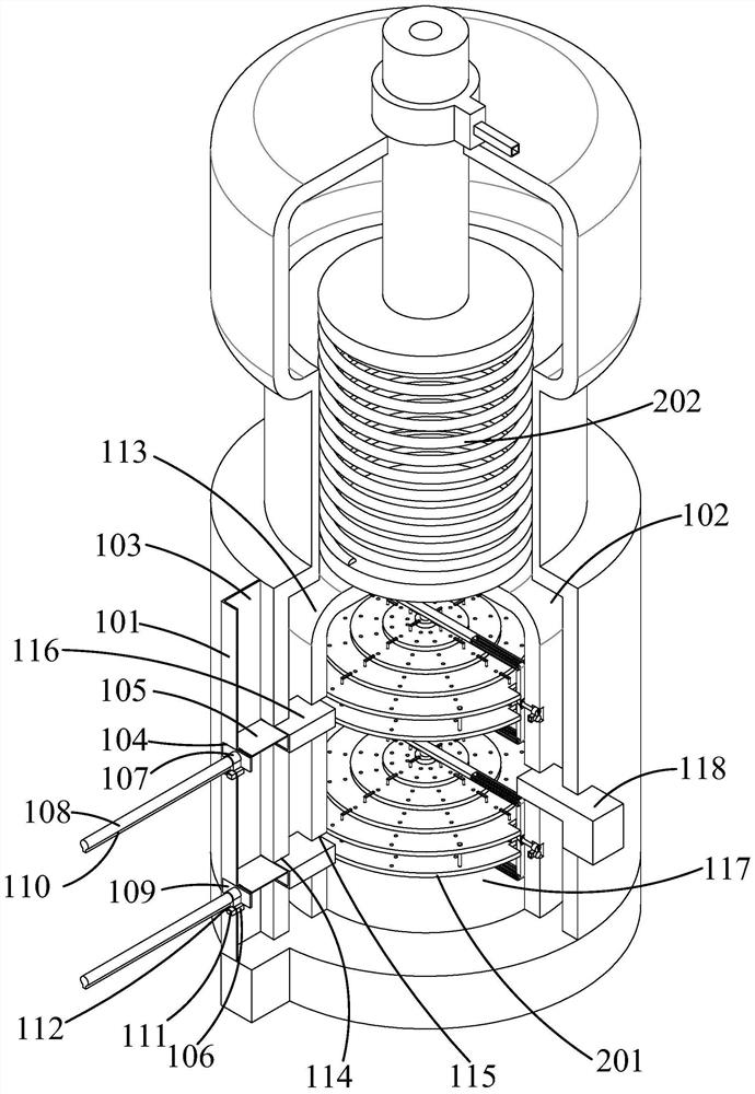
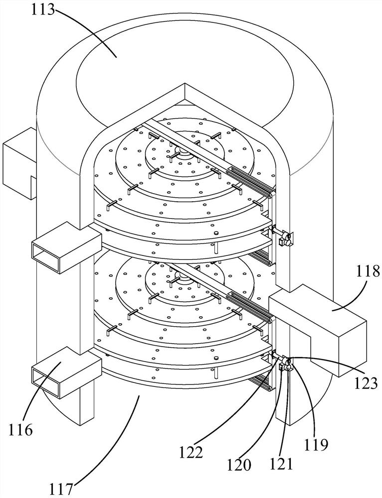
[0029] like Figure 1-Figure 7 As shown, the present invention is described in detail. For the convenience of description, the orientations mentioned below are now stipulated as follows: figure 1 The up, down, left, right, front and back directions of the projection relationship are the same. The biomass fuel particle combustion equipment of the present invention includes a furnace barrel 100, a filling furnace 101 is fixed on one side of the furnace barrel 100, and a furnace barrel inner cavity 102 is arranged in the furnace barrel 100. The filler The furnace 101 is provided with a feeding assembly 200 for pushing fuel into the equipment, and the furnace barrel 100 is provided with a furnace barrel cavity 102, which is filled with water. A grate assembly 201 is provided, a smoke exhaust assembly 202 for exhausting smoke is provided in the inner cavity 102 of the furnace barrel, and an ash discharge assembly 203 for removing furnace ash is arranged at the bottom of the furnace b...


PUM


Abstract

The invention discloses biomass fuel particle combustion equipment. The biomass fuel particle combustion equipment structurally comprises a furnace barrel; a filler furnace is fixedly arranged on one side of the furnace barrel; a furnace barrel inner cavity is formed in the filler furnace; a feeding component used for pushing fuel into the equipment is arranged in the furnace barrel inner cavity; the furnace barrel inner cavity is formed in the furnace barrel; the furnace barrel inner cavity is filled with water; a fire grate component used for achieving fuel combustion is arranged in the furnace barrel inner cavity;a smoke discharging component used for achieving smoke discharging is arranged in the furnace barrel inner cavity;and an ash discharging component used for taking out furnace ash is arranged at the bottom of the furnace barrel. According to the biomass fuel particle combustion equipment, fuels can be automatically filled,fire grates can be driven to be staggered in a laminated mode, and can rotate to enable the fuel to be sufficiently burned, so that the combustion efficiency is improved, and the flue can be fully utilized to heat water inside.

Description

technical field [0001] The invention belongs to the field of energy technology, in particular to biomass fuel particle combustion equipment. Background technique [0002] The disadvantages of the prior art are that for small boiler equipment, the structure of the boiler is relatively simple, the function is single, and the automatic filling of fuel cannot be realized. The grate structure is simple, and the combustion efficiency cannot be increased by driving the grate. The flue heats the water liquid inside. For this reason, people have carried out long-term exploration, put forward various solutions. [0003] For example, the Chinese patent literature discloses [a new type of vertical atmospheric pressure hot water boiler equipment application number: 201520588428.2], including body, furnace bottom, smoke pipe, water level gauge, flange plate, water whistle, outlet pipe seat, exhaust Pipe, return pipe seat, hand hole and hot water nozzle, the bottom of the furnace body is...

Claims


Application Information

Patent Timeline
IPC IPC(8): F23B40/00F23J1/06
CPCF23B40/00F23J1/06
Inventor 唐炜张津瑜
Owner 上海旖琥环境工程技术发展有限公司
Why Eureka
Try Eureka