Check patentability & draft patents in minutes with Patsnap Eureka AI!

Phase compensation method and related phase locked loop module

A phase-locked loop, phase compensation technology, applied in the direction of automatic power control, electrical components, etc., can solve the problems of the phase-locked loop circuit 10 calibration speed drop, deviating from the real phase of known data, etc.

Inactive Publication Date: 2019-02-05
MEDIATEK INC
View PDF7 Cites 0 Cited by
  • Summary
  • Abstract
  • Description
  • Claims
  • Application Information

AI Technical Summary

Problems solved by technology

However, when the channel quality (such as SNR) is low, the maximum likelihood phase φ ES_ML Will greatly deviate from the real phase of the known data, but the calibration speed of the phase-locked loop circuit 10 will be greatly reduced

Method used


Image

  • Phase compensation method and related phase locked loop module
  • Phase compensation method and related phase locked loop module
  • Phase compensation method and related phase locked loop module

Examples


Embodiment Construction

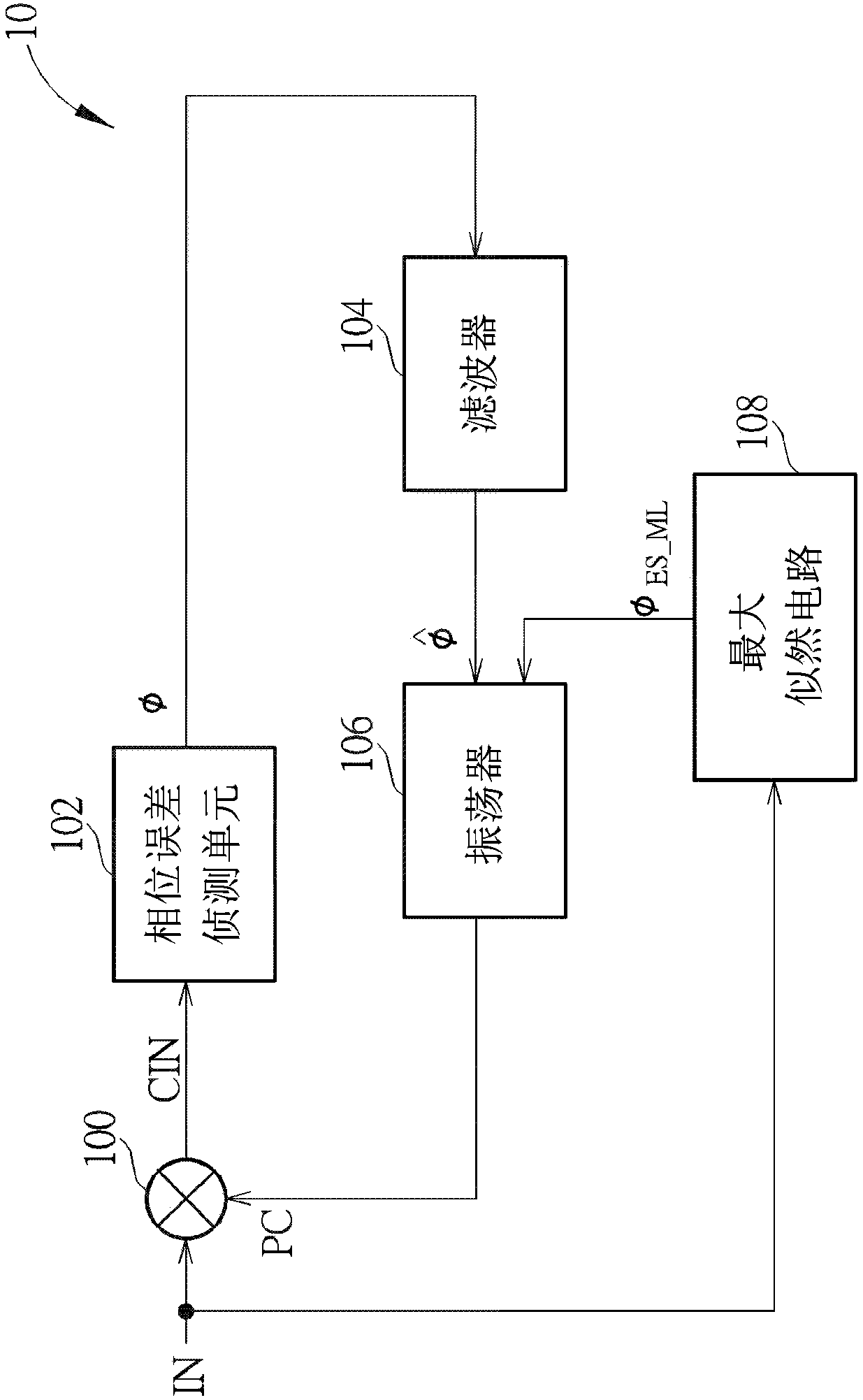
[0034] Please refer to figure 2 , figure 2 It is a schematic diagram of a phase-locked loop module 20 according to an embodiment of the present invention. The PLL module 20 can be installed in a communication device for correcting the phase error φ of an input signal IN. The communication device can be, for example, a smart phone, a tablet computer, a notebook computer, and a set-top box, but is not limited thereto. like figure 2 As shown, the PLL module 20 includes a multiplier 200, a phase error detection unit 202, a filter 204, an oscillator 206, a maximum likelihood circuit 208, a data auxiliary circuit 210, a monitoring unit 212 and A multiplexer 214. The operation mode of the multiplier 200, the phase error detection unit 202, the filter 204, the oscillator 206 and the maximum likelihood circuit 208 in the phase-locked loop module 20 is the same as that of the multiplier 100, the phase error detection in the phase-locked loop circuit 10 The unit 102 , the filter ...


PUM


Abstract

The invention relates to a phase compensation method which is used for a phase locked loop module of a communication device and comprises the step of: according to an input signal, deciding to outputa maximum likelihood phase to an oscillator of the phase locked loop module, or outputting a digital assisted phase error to a filter of the phase locked loop module, wherein the maximum likelihood phase is a phase generated when known data in the input signal is estimated by utilizing a maximum likelihood method, and the digital assisted phase error is a phase error generated when the known datain the input signal is estimated by using a data assisted method.

Description

technical field [0001] The present invention refers to a phase compensation method and a related phase-locked loop module, especially a phase compensation method capable of adjusting and predicting a phase error of unknown data according to channel quality, a related phase error prediction unit and a phase-locked loop module. Background technique [0002] A Phase Locked-Loop (PLL) circuit is used to generate a periodic output signal, and the periodic output signal is expected to have a fixed phase relationship with a periodic input signal. Phase-locked loop circuits are widely used in various circuit systems, such as data and clock recovery circuits (Clock and DataRecovery), transceiver modules (Transceiver) or frequency generators (Frequency Synthesizer) of wireless communication systems. limited to this. [0003] Please refer to figure 1 , figure 1 It is a schematic diagram of a PLL circuit 10 in the prior art. The PLL circuit 10 is used to calibrate an input signal IN...

Claims


Application Information

Patent Timeline
Patent Type & Authority Applications(China)
IPC IPC(8): H03L7/091H03L7/085H03L7/093
CPCH03L7/085H03L7/091H03L7/093
Inventor 卓庭楠郑凯文童泰来
Owner MEDIATEK INC
Features
  • R&D
  • Intellectual Property
  • Life Sciences
  • Materials
  • Tech Scout
  • Unparalleled Data Quality
  • Higher Quality Content
  • 60% Fewer Hallucinations
Learn More