
Fire escape device

An escape device and fire technology, applied in the field of fire escape devices, can solve the problems of many stairs turning, lack of implementation plans for slow descent devices, and long time.

Inactive Publication Date: 2019-02-12
张煌辉
View PDF1 Cites 2 Cited by
  • Summary
  • Abstract
  • Description
  • Claims
  • Application Information

AI Technical Summary

Problems solved by technology

[0002] In the event of a fire, earthquake, etc., people living in high-rise buildings cannot take the elevator downstairs. If they take the stairs to go downstairs, it will take a long time, the people will be crowded, and the stairs will turn many times. Therefore, it is ideal to install escape devices on high buildings. The existing escape devices There are pipe-type escape devices, such as patent application number 201610022277.3, and the patent name is: an escape pipe, which includes an indoor fixed frame, a curved pipe and a straight pipe, and the straight pipe is composed of multi-section double-wall corrugated pipes , the double-wall corrugated pipe adopts the structure of two corrugated pipe sets, the top of the straight pipe is provided with a safety hook, the safety hook is fixedly connected with a descending device, and the speed controller is wound on the descending device to connect with the safety belt, but the descending device lack of concrete implementation

Method used


Image

  • Fire escape device
  • Fire escape device
  • Fire escape device

Examples


Embodiment Construction

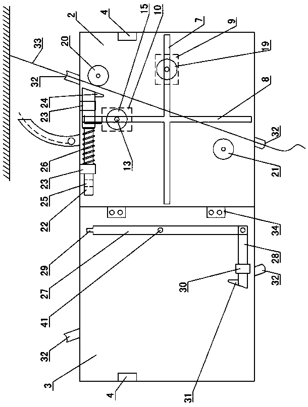
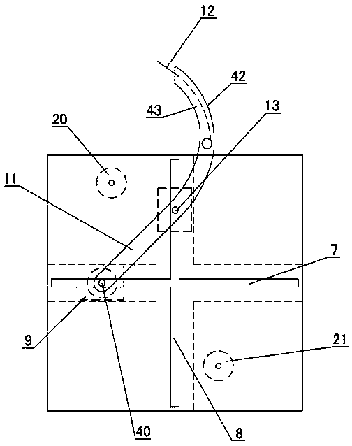
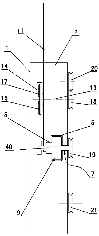
[0015] The invention relates to a fire escape device, such as figure 1 — Figure 8As shown, the rear cover 1, the main board 2 and the front cover 3 of the escape device are included, and the main board 2 and the front cover 3 are rotationally connected. It is used to fix the outside of the main board 2 and the front cover 3. A horizontal trapezoidal groove 5 and a vertical trapezoidal groove 6 are arranged on the main board 2, and the bottom surfaces of the horizontal trapezoidal groove 5 and the vertical trapezoidal groove 6 are respectively formed with transverse through grooves 7 and Longitudinal through groove 8, horizontal slider 9 and vertical slider 10 are respectively arranged in horizontal trapezoidal groove 5 and vertical trapezoidal groove 6, horizontal slider 9 and vertical slider 10 are connected by connecting rod 11, and the upper end of connecting rod 11 is connected with insurance One end of the rope 12, the other end of the safety rope 12 is connected with a...


PUM


Abstract

The invention provides a fire escape device. The fire escape device comprises a rear cover plate, a main plate and a front cover plate. The main plate is provided with a transverse trapezoidal groove,a longitudinal trapezoidal groove, a transverse slot, a longitudinal slot, an upper fixed pulley, a lower fixed pulley and a cross pull rod. A transverse sliding block and the longitudinal sliding block are arranged in the transverse trapezoidal groove and the longitudinal trapezoidal groove correspondingly and are connected through a connecting rod. The upper end of the connecting rod is connected with a safety rope and a safety belt and used for being fixed to a human body. The longitudinal sliding block is connected with the connecting rod through a second fixed rotary shaft and penetratesthrough the longitudinal slot to slide up and down. The two ends of the second fixed rotary shaft are provided with a brake wheel and a longitudinal pulley correspondingly. The transverse sliding block is connected with the lower end of the connecting rod through a first fixed rotary shaft and penetrates through the transverse slot to slide left and right. The two ends of the first fixed rotary shaft are provided with a warning device and a transverse pulley correspondingly. A rope locking brake at the head of the cross pull rod makes contact with the upper fixed pulley. A swing rod and a cross push rod are arranged on the front cover plate. A convex block at the head of the swing rod is matched with a groove at the other end of the cross push rod. An inclined push plate at the tail of the cross push rod makes contact with the longitudinal pulley. The main plate and the front cover plate are both provided with circular arc grooves for arrangement of an escape rope.

Description

technical field [0001] The invention relates to a fire escape device. Background technique [0002] In the event of a fire, earthquake, etc., people living in high-rise buildings cannot take the elevator downstairs. If they take the stairs to go downstairs, it will take a long time, the people will be crowded, and the stairs will turn many times. Therefore, it is ideal to install escape devices on high buildings. The existing escape devices There are pipe-type escape devices, such as patent application number 201610022277.3, and the patent name is: an escape pipe, which includes an indoor fixed frame, a curved pipe and a straight pipe, and the straight pipe is composed of multi-section double-wall corrugated pipes , the double-wall corrugated pipe adopts the structure of two corrugated pipe sets, the top of the straight pipe is provided with a safety hook, the safety hook is fixedly connected with a descending device, and the speed controller is wound on the descending devic...

Claims


Application Information

Patent Timeline
IPC IPC(8): A62B1/10A62B1/18
CPCA62B1/10A62B1/18
Inventor 张煌辉黄米初
Owner 张煌辉
Learn More