Electric landing gears and pneumatic speed sensor
A technology of speed sensor and landing gear, which is applied to bicycle sensors, motor vehicles, transportation and packaging, etc. It can solve the problems of not being too low in speed, not easy to hold steady, etc., and achieve the effect of stable driving and parking
- Summary
- Abstract
- Description
- Claims
- Application Information
AI Technical Summary
Problems solved by technology
Method used
Image

Examples
Embodiment 1
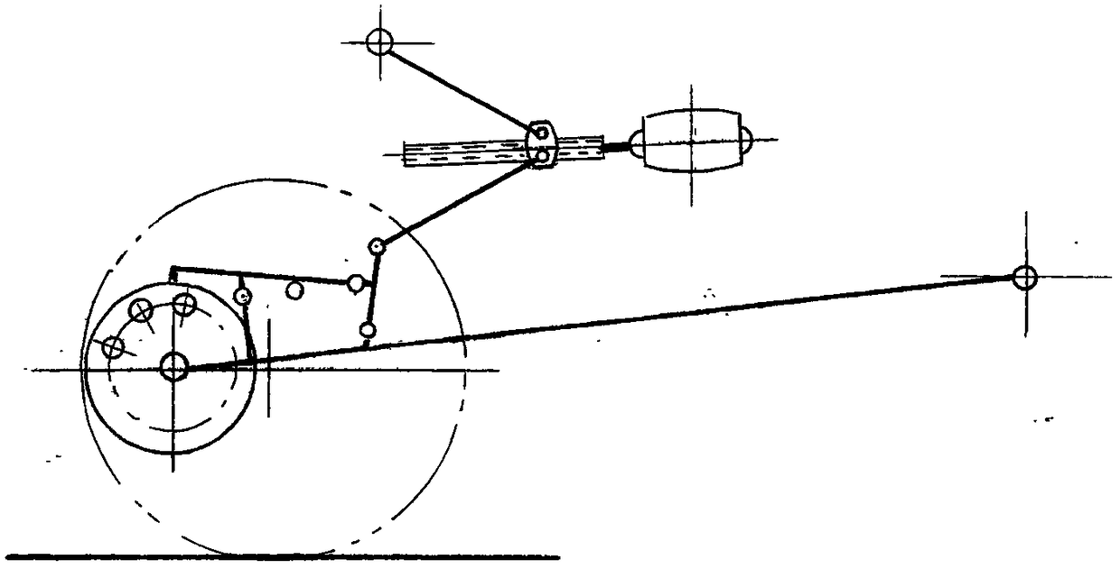
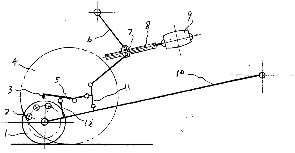
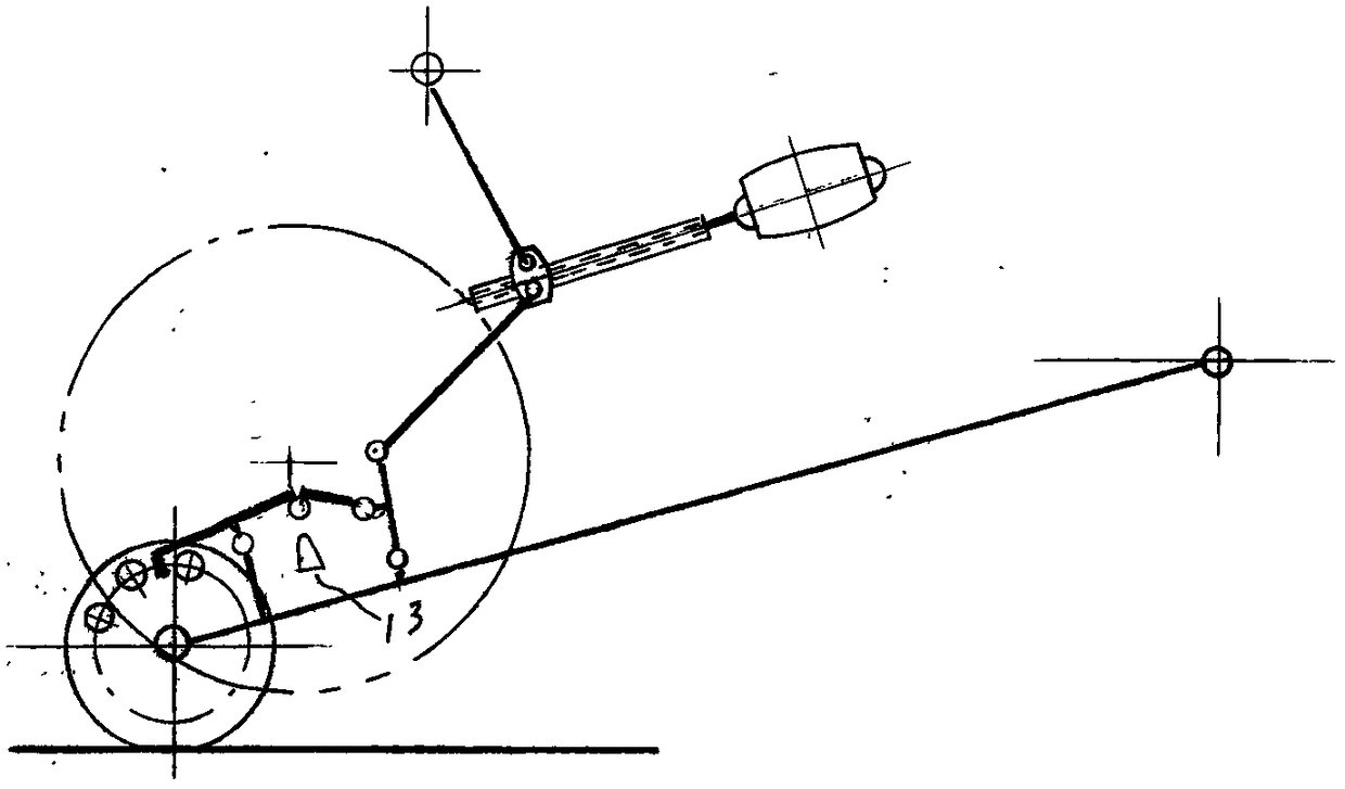
[0021] Such as figure 1 , figure 2 , image 3 Shown is an electric landing gear and landing wheels that can be raised and lowered.
[0022] Below the landing gear that can be raised and lowered is a flat-fork swing rod 10 with one end movably connected to the body and one end that can swing up and down. A landing wheel 1 is installed in the flat fork fork of the flat-fork swing rod 10. The steel ring side of the landing wheel 1 is The ratchet wheel 2 formed by several ratchet teeth and connected with the steel ring as a whole. At the position close to the ratchet wheel 2, a fixed vertical rod 12 fixedly connected to the horizontal fork swing rod 10 is erected on the flat fork swing rod 10, and the fixed vertical rod 12 A little behind, there is a swinging pole 11 that is movably connected to the flat-fork pendulum rod 10 and can swing back and forth. The top of the swinging pole 11 is a set of curved extension struts 6 that can drive the flat-fork pendulum rod 10 to swing up and ...
Embodiment 2
[0027] Such as Figure 4-12 Shown is an electric vehicle stamped and formed from a thin plate. Under the belly on the left and right sides of the electric vehicle, there are a set of landing wheels 1 and 15 that are lifted and lowered by a landing gear. Such as Figure 4 , Image 6 It is a diagram of the landing wheels 1 and 15 on the left and right sides being lifted. Such as Figure 7 , Picture 9 It is a diagram showing the landing wheels 1 and 15 on the left and right sides descend to the ground. Such as Picture 10 , Picture 12 It is a diagram showing the landing wheels 1 and 15 on the left and right sides land and the rear wheel 4 is raised.
Embodiment 3
[0029] Such as Figure 13 Shown is a pneumatic speed sensor. On the axles of the front or rear wheels of the electric vehicle, or on the side of the wheel, there is a set of fan blades 23 like a blower, a pneumatic speed sensor 25 driven by wheels, a pneumatic speed sensor 25 The outer shell 22 is opened with a damper 19 that communicates with the inside and the outside. The damper 19 is covered with a layer of pneumatic membrane 21 that can be inflated by wind. Just outside the pneumatic membrane 21 is a micro switch 20 that can be inflated by the pneumatic membrane 21. The movable switch 20 is connected to the motor 9 again. It is also possible to install a wind-driven door leaf 24 at the door opening of the air door 19. Outside the door leaf 24 is a micro switch 20 that can be pressed by the door leaf. The micro switch 20 is then connected to the motor 9.
PUM
 Abstract
Description
Claims
Application Information
 - R&D Engineer
- R&D Manager
- IP Professional
- Industry Leading Data Capabilities
- Powerful AI technology
- Patent DNA Extraction
Browse by: Latest US Patents, China's latest patents, Technical Efficacy Thesaurus, Application Domain, Technology Topic.
© 2024 PatSnap. All rights reserved.Legal|Privacy policy|Modern Slavery Act Transparency Statement|Sitemap