
Atomic layer deposition system

A technology of atomic layer deposition and precursors, applied in coatings, metal material coating processes, gaseous chemical plating, etc., can solve the problems of affecting the quality of deposited films, pressure fluctuations in reaction chambers, waste of reaction precursors, etc., to achieve Improve film deposition quality and process stability, ensure pressure balance, and reduce waste

Active Publication Date: 2019-02-12
BEIJING NAURA MICROELECTRONICS EQUIP CO LTD
View PDF3 Cites 9 Cited by
  • Summary
  • Abstract
  • Description
  • Claims
  • Application Information

AI Technical Summary

Problems solved by technology

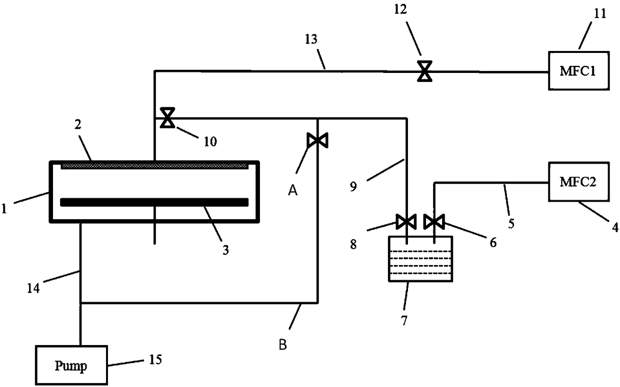
The precursor is directly discharged into the vacuum pump 15, resulting in waste of the precursor
[0006] Therefore, in order to achieve rapid switching between atomic layer deposition reaction steps, when a reaction precursor is not passed into the chamber, it is directly connected to the vacuum pump, resulting in waste of reaction precursors, which is not conducive to industrial cost control
In addition, the precursors often need to be carried into the reaction chamber by the carrier gas, and the reaction precursors are directly connected to the vacuum pump, which will cause pressure fluctuations in the reaction chamber and affect the quality of the deposited film.

Method used


Image

  • Atomic layer deposition system
  • Atomic layer deposition system

Examples


Embodiment Construction

[0025] In order to make the content of the present invention clearer and easier to understand, the content of the present invention will be further described below in conjunction with the accompanying drawings. Of course, the present invention is not limited to this specific embodiment, and general replacements known to those skilled in the art are also covered within the protection scope of the present invention.

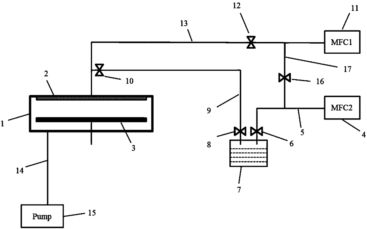
[0026] In the present invention, a pressure balance pipeline is set between the carrier gas pipeline and the dilution gas pipeline to reduce the waste of precursors. At the same time, when the precursor gas pipeline is closed, the pressure fluctuation of the reaction chamber will not be caused, and the reaction chamber chamber pressure balance.

[0027] The following is attached figure 2 The present invention will be described in further detail with specific examples. It should be noted that the drawings are all in a very simplified form, using imprecise scales,...


PUM


Abstract

The invention provides an atomic layer deposition system. The atomic layer deposition system is characterized in that a precursor source is connected with one end of a carrier gas pipeline and one endof a precursor gas pipeline, carrier gas in the carrier gas pipeline passes through the carrier gas pipeline and flows through the precursor source, the carrier gas carries precursor and flows alongthe precursor gas pipeline, one end of a dilution gas pipeline is connected with a reaction chamber, the other end of the precursor gas pipeline is connected to the side, close to the reaction chamber, of the dilution gas pipeline, and therefore, the carrier gas carrying precursor is mixed with the dilution gas, passes through one end of the dilution gas pipeline and flows into the reaction chamber; one end of a pressure balance pipeline is connected with the dilution gas pipeline, and the other end of the pressure balance pipeline is connected with the carrier gas pipeline, so that when precursor gas is not conveyed into the reaction chamber, carrier gas flows to the dilution gas pipeline from the carrier gas pipeline, waste of precursor is reduced, meanwhile, the carrier gas is mixed with the dilution gas and then enters the reaction chamber, and pressure balance and technology stability of the reaction chamber are ensured.

Description

technical field [0001] The invention relates to the technical field of semiconductor manufacturing, in particular to a system for reducing the consumption of atomic layer deposition reaction precursors. Background technique [0002] Atomic Layer Deposition technology (Atomic Layer Deposition) is a semiconductor film preparation technology, which was first called atomic layer epitaxy technology and was proposed by Finnish scholar Tuomo Suntola. [0003] With the development of semiconductor technology, electronic components have entered the nm-level process, which puts forward higher requirements for the quality of deposited films in semiconductor technology, especially film thickness and step coverage. Atomic layer deposition technology has many advantages in thin film deposition, such as: excellent step coverage, precise thickness control, low reaction temperature, excellent film performance, etc., and is considered to be one of the most potential thin film preparation tech...

Claims


Application Information

Patent Timeline
Patent Type & Authority Applications(China)
IPC IPC(8): C23C16/455
CPCC23C16/45544
Inventor 赵雷超李春雷秦海丰纪红张芳兰云峰王勇飞王洪彪文莉辉储芾平
Owner BEIJING NAURA MICROELECTRONICS EQUIP CO LTD
Learn More