Giant concrete-filled steel tubular inclined column and inclined strut transferring joint structure

A technology of steel pipe concrete and transfer nodes, which is applied in the direction of building structure and construction, and can solve the problems of reduced space for transfer floors, low bearing capacity of reinforced concrete components, and difficulties in pouring and tamping concrete for welding construction, so as to solve the welding workload The effect of large size, guaranteed construction quality and good lateral force resistance

Pending Publication Date: 2019-02-12
CHINA IPPR INT ENG
View PDF0 Cites 0 Cited by
  • Summary
  • Abstract
  • Description
  • Claims
  • Application Information

AI Technical Summary

Problems solved by technology

The bearing capacity of reinforced concrete members is low. In order to meet the safety requirements, the cross-sectional size of the inclined column and the volume of the joints are large, which will reduce the use of space in the transfer floor building and inconvenience the passage of pipelines.
[0007] (2) Node construct

Method used


Image

  • Giant concrete-filled steel tubular inclined column and inclined strut transferring joint structure
  • Giant concrete-filled steel tubular inclined column and inclined strut transferring joint structure
  • Giant concrete-filled steel tubular inclined column and inclined strut transferring joint structure

Examples


Example Embodiment

[0073] The specific embodiments of the present invention will be described in detail below in conjunction with the drawings, but they are not used to limit the protection scope of the present invention.

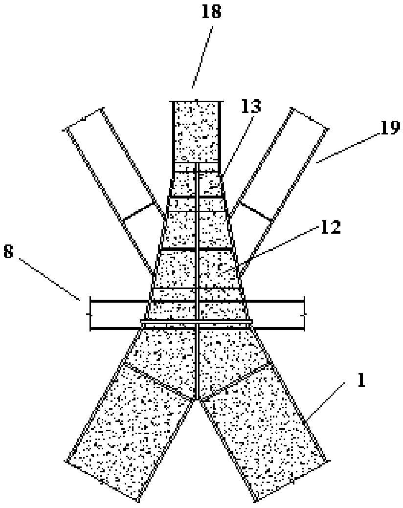
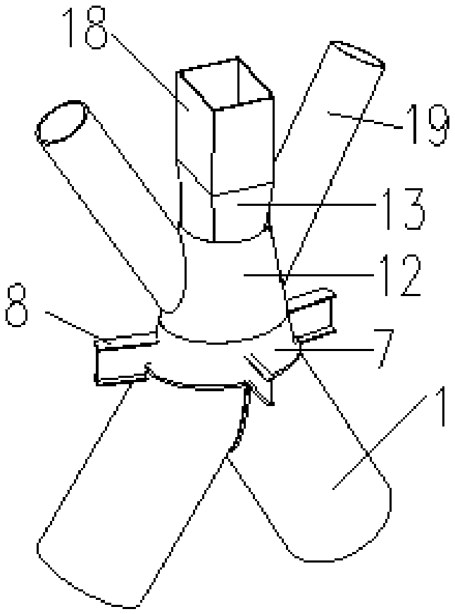
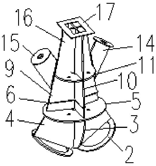
[0074] See attached Figure 1-3 In the embodiment, a giant concrete-filled steel tube diagonal column and diagonal brace conversion node structure, including diagonal pillar 1, frame column 18, diagonal brace 19, conversion member and frame beam 8, diagonal brace 19 is fixedly connected to the conversion member, and the frame column 18 is fixedly connected to the conversion member, the conversion member is fixedly arranged at the top end of the inclined pillar 1, and the frame beam 8 is fixedly or hingedly connected to the conversion member. The conversion member includes three parts: an ellipse conversion piece 7, a large circle-to-small-circle conversion piece 12, and a circle-to-square conversion piece 13. The ellipse conversion piece 7 is connected to the diagonal strut 1, a...


PUM


Abstract

The invention provides a giant concrete-filled steel tubular inclined column and inclined strut transferring joint structure. The giant concrete-filled steel tubular inclined column and inclined struttransferring joint structure comprises inclined supporting columns (1), a frame column (18), inclined struts (19), a transferring element and a frame beam (8), the inclined struts (19) are fixedly connected to the transferring element, the frame column is fixedly connected to the transferring element, the transferring component is fixedly arranged at the top ends of the inclined supporting columns, and the frame beam is fixedly connected or hinged to the transferring element. The transferring element comprises an elliptical transferring piece, a great circle-to-small circle transferring pieceand a circle-to-square transferring piece, wherein the elliptical transferring piece, the great circle-to-small circle transferring piece and the circle-to-square transferring piece are sequentiallyand fixedly connected. The elliptical transferring piece is connected with the inclined supporting columns, the great circle-to-small circle transferring piece is connected with the inclined struts, and the circle-to-square transferring piece is connected with the frame column. Annular stiffening rib plates and longitudinal stiffening rib plates are arranged in the inclined supporting columns, theframe column and the inclined struts, vertical internal rib plates parallel to the surfaces of the inclined struts, vertical internal rib plates perpendicular to the surfaces of the inclined strut and annular stiffening rib plates are arranged in the transferring element, and the inclined supporting columns are connected with the transferring element through a horizontal circular transferring ribplate and a vertical arc-shaped transferring rib plate.

Description

technical field [0001] The invention relates to the technical field of building structures, in particular to a giant supporting frame structure for super high-rise building structures. Background technique [0002] As the functions and forms of high-rise and super high-rise buildings continue to diversify, the application of transfer floors is becoming more and more extensive. The inclined column transfer structure has transfer members, which mainly bear the axial load, has the characteristics of short force transmission path and small cross-sectional size of the transfer members, which is beneficial to the use of architectural space, so it has a wide application prospect. In addition, because the transition member mainly bears axial load, it is suitable to adopt the CFST member. The size of steel pipe concrete members is smaller than that of traditional reinforced concrete members, and it saves formwork and does not need to bind steel bars. The construction progress is fas...

Claims


Application Information

Patent Timeline
IPC IPC(8): E04B1/58E04B1/18
CPCE04B1/185E04B1/5837
Inventor 张松张同亿王宁肖自强张特
Owner CHINA IPPR INT ENG
Why Eureka
Try Eureka