
Installation method of submarine pipeline buckling detector

A submarine pipeline and installation method technology, which is applied in the direction of special pipes, pipe components, pipes/pipe joints/pipe fittings, etc., can solve the problems of loosening and falling off of wire rope nuts, adhesion of steel wire rope and welding spot welds of submarine pipelines, etc., to achieve smooth movement, The effect of reducing the probability of falling into the submarine pipeline and improving construction efficiency

Inactive Publication Date: 2019-02-12
OFFSHORE OIL ENG
View PDF6 Cites 3 Cited by
  • Summary
  • Abstract
  • Description
  • Claims
  • Application Information

AI Technical Summary

Problems solved by technology

[0003] The main purpose of the present invention is to overcome the above-mentioned shortcomings existing in the prior art, and provide a kind of installation method of buckling detector of submarine pipeline, which not only solves the problem of welding seam adhesion at the welding point of steel wire rope and submarine pipeline, but also makes buckling detector The movement in the submarine pipeline is smoother, which greatly improves the detection speed; moreover, it solves the problem of the nut loosening and falling off of the connecting snap ring between the steel wire rope and the buckling detector, and greatly reduces the probability of the buckling detector falling into the submarine pipeline; that is Improve construction efficiency and avoid construction risks

Method used


Image

  • Installation method of submarine pipeline buckling detector
  • Installation method of submarine pipeline buckling detector
  • Installation method of submarine pipeline buckling detector

Examples


Embodiment Construction

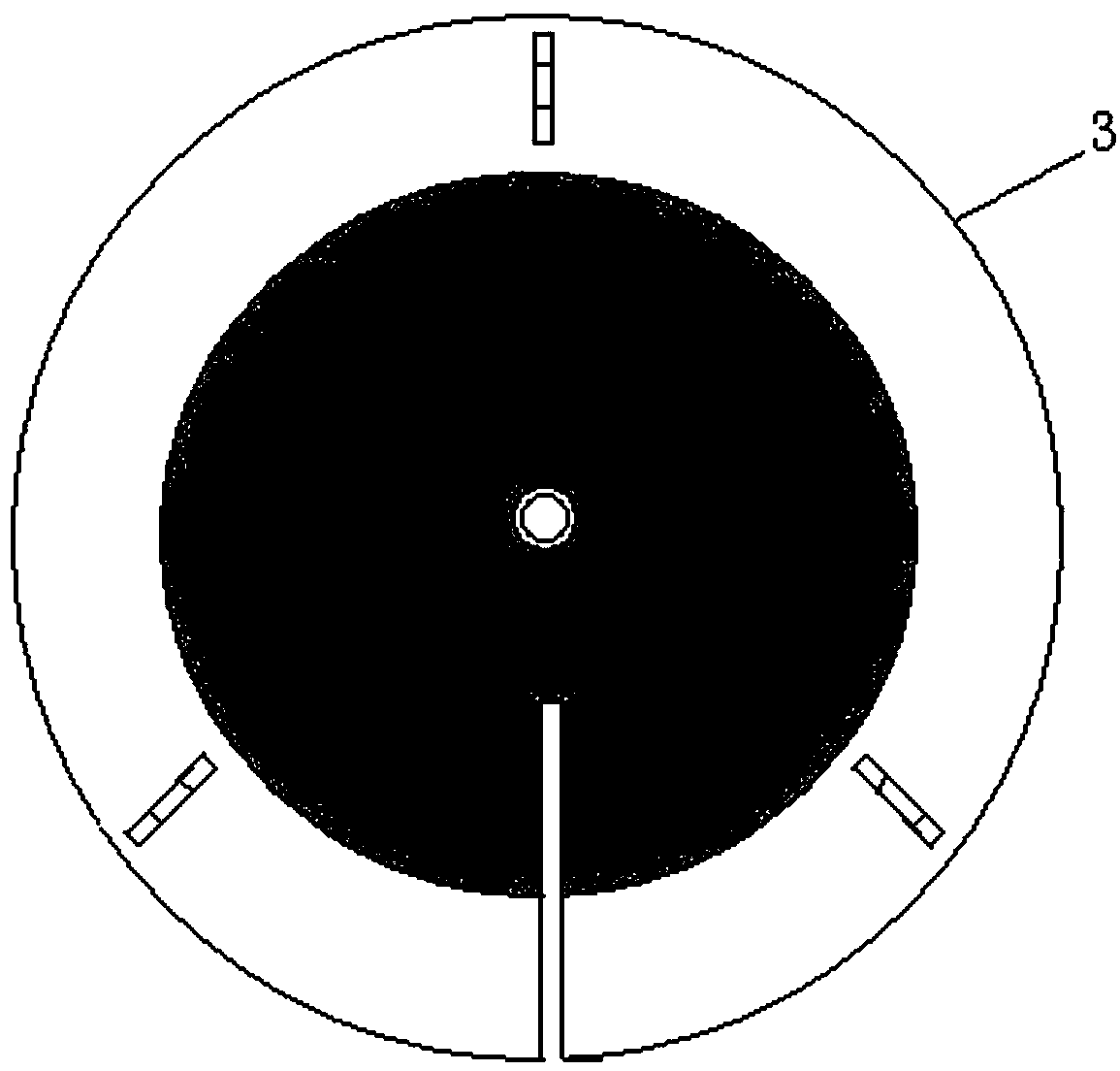
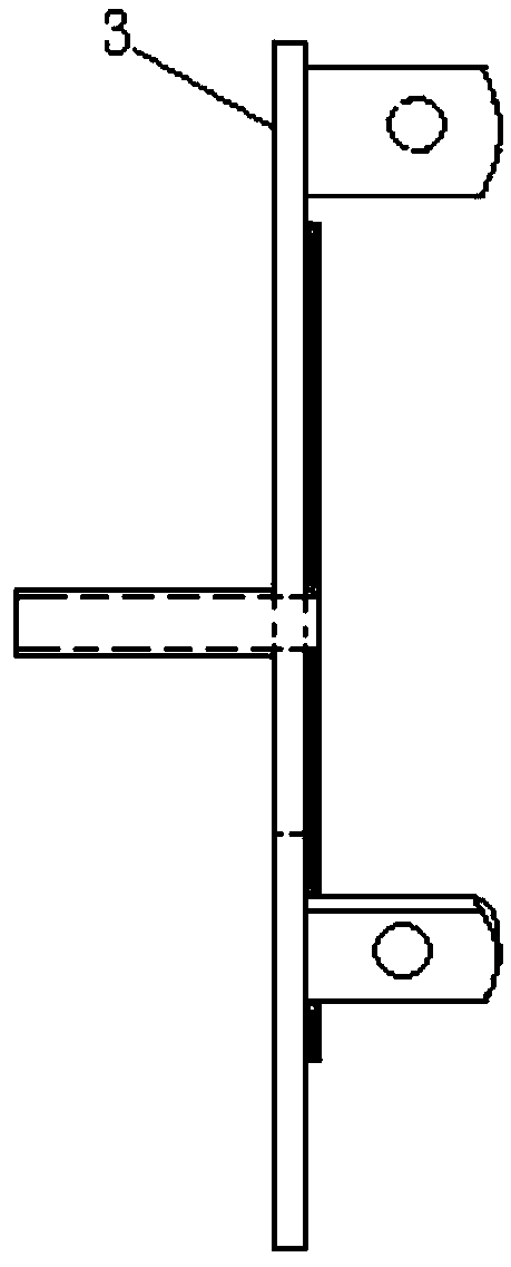
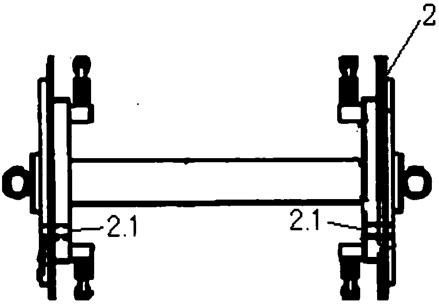
[0027] Such as figure 1 — Figure 4 As shown, the present invention adopts the following installation steps:

[0028] The first step: construction preparation, including:

[0029] 1) Determine the length of the required wire rope 5 according to the set position of the buckling detector 2 in the submarine pipeline 1, and mark the wire rope 5;

[0030] 2) According to the position of the welding point 7 of the submarine pipeline 1, determine the position of the copper pipe 4 on the steel wire rope 5;

[0031] 3) Set a section of copper pipe 4 on the set position of the steel wire rope 5 and fix it;

[0032] 4) Air vents 2.1 are provided on the buckling detector 2, and the vent holes 2.1 are arranged at any position on the baffles on both sides of the buckling detector, and each baffle is provided with a small hole;

[0033] Step 2: Connect the entire steel wire rope 5 to the buckling detector 2 through the snap ring 6, and put the buckling detector 2 into the submarine pipel...


PUM


Abstract

An installation method of a submarine pipeline buckling detector comprises the following installation steps that firstly, venting holes are formed in the buckling detector; secondly, the buckling detector is put into a submarine pipeline; thirdly, pipe openings of the submarine pipeline are sealed; fourthly, the submarine pipeline is filled with the compressed air, and the buckling detector forwards moves to the interior of the submarine pipeline; fifthly, a steel wire rope stops moving forwards; sixthly, air inflation of the submarine pipeline stops; seventhly, the fourth step to the sixth step are repeated until the buckling detector arrives at the set position of the interior of the submarine pipeline; eighthly, a steel wire rope with a copper pipe and the steel wire rope which enters the submarine pipeline are connected; and ninthly, the copper pipe is placed at the position of a welding point in the submarine pipeline. By the adoption of the installation method of the submarine pipeline buckling detector, the problem that weld seams at the welding points of the steel wire ropes and the submarine pipeline are adhesive is solved, movement of the buckling detector in the submarine pipeline can be smoother, and the detection speed is increased. In addition, the problem that nuts of connecting snap rings of the buckling detector are loosened and fall down is solved, and the probability of the phenomenon that the buckling detector falls in the submarine pipeline is reduced.

Description

technical field [0001] The invention relates to a pipeline buckling detector, in particular to an installation method for a submarine pipeline buckling detector. It belongs to the field of marine engineering. Background technique [0002] At present, in order to confirm whether there is buckling damage to the subsea pipeline during offshore laying of the subsea pipeline, real-time detection of the subsea pipeline is required. When testing, first connect one end of the buckling detector to the steel wire rope, then place the buckling detector in the submarine pipeline, then use a baffle to block the nozzle of the submarine pipeline, and blow compressed air into the submarine pipeline, Pushed by the pressure, the buckling detector gradually enters the depth of the submarine pipeline. And according to the length of the wire rope connected to the buckling detector in the submarine pipeline, it is determined whether the buckling detector has reached a designated position in the...

Claims


Application Information

Patent Timeline
Patent Type & Authority Applications(China)
IPC IPC(8): F16L55/32F16L55/40F16L101/30
CPCF16L55/32F16L55/40F16L2101/30
Inventor 陈永訢梁超于文太燕晖杜永军李建楠李斌牛强吴业卫高庆有
Owner OFFSHORE OIL ENG
Learn More