
Test device and test method for seepage and water inrush of rock formation bottom plate

A test device and bottom plate technology, which is applied in the direction of measuring device, permeability/surface area analysis, and application of stable tension/pressure to test material strength, etc., can solve the problem of not being able to simulate the seepage characteristics of the rock floor well, and achieve enhanced sealing performance, guaranteed accuracy, and the effect of overcoming sealing problems

Inactive Publication Date: 2019-02-12
CENT SOUTH UNIV
View PDF4 Cites 4 Cited by
  • Summary
  • Abstract
  • Description
  • Claims
  • Application Information

AI Technical Summary

Problems solved by technology

[0004] Patent 200610166463.0 discloses a curved rock sample permeability test device. The rock sample installed in the cylinder is simultaneously squeezed and pushed up. The rock sample bends and deforms while infiltrating. The speed changes rapidly, so as to simulate the characteristics of water inrush, and verify that water inrush is a process of seepage instability accompanied by structural damage, but the rock floor is always under the action of high water pressure, so the above patents cannot simulate pressure well Seepage characteristics of rock formation floor under bending moment under water action

Method used


Image

  • Test device and test method for seepage and water inrush of rock formation bottom plate
  • Test device and test method for seepage and water inrush of rock formation bottom plate

Examples


Embodiment Construction

[0027] The following will clearly and completely describe the technical solutions in the embodiments of the present invention with reference to the accompanying drawings in the embodiments of the present invention. Obviously, the described embodiments are only some, not all, embodiments of the present invention. Based on the embodiments of the present invention, all other embodiments obtained by persons of ordinary skill in the art without creative efforts fall within the protection scope of the present invention.

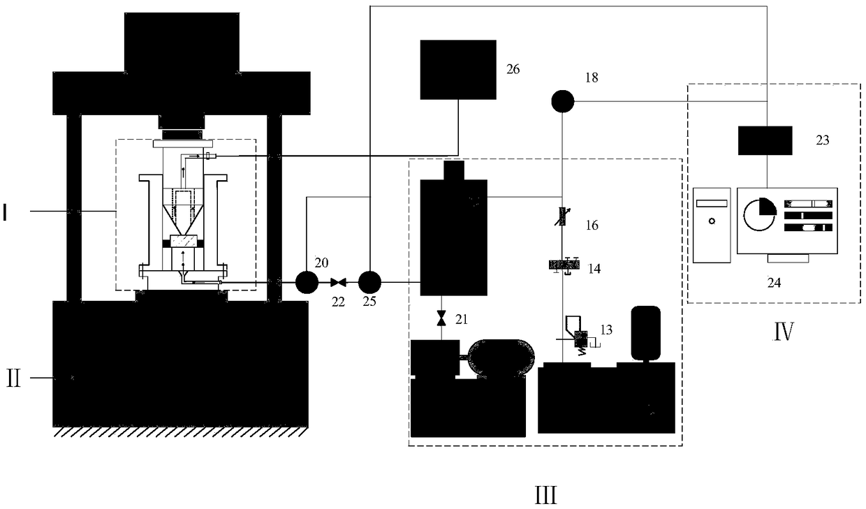
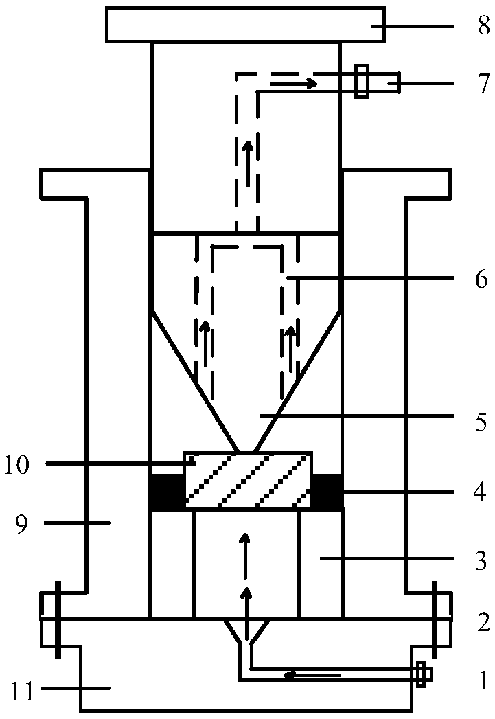
[0028] see figure 1 and figure 2 , a seepage water inrush test device for a rock floor, including an axial loading system II, a permeameter I and a data acquisition system IV, and the permeameter I is set between the bearing platform and the loading head of the axial loading system II. Concretely, the permeation instrument I includes a cylinder 9 arranged on the bearing platform. The indenter 8 is matched and slidably arranged below the loading head in the cylind...


PUM


Abstract

The invention discloses a test device and a test method for seepage and water inrush of a rock formation bottom plate. The device comprises an axial loading system and a permeation instrument. The permeation instrument comprises a cylinder barrel arranged between a bearing platform and a loading head of the axial loading system and a pressing head slidably arranged in the cylinder barrel. A supporting ring is fixedly arranged in the cylinder barrel. The bottom of the pressing head is tapered and faces the center of the supporting ring. A space for placing a bottom plate rock sample and a sealant material is arranged between the pressing head and the supporting ring. The cylinder barrel is located in a cavity between the bottom plate rock sample and a bottom plate of the cylinder barrel, and is filled with high-pressure water through a water inlet pipe. A flowmeter and a water pressure sensor are arranged on the water inlet pipe. According to the test device and the test method for seepage and water inrush of the rock formation bottom plate, bending deformation of the rock sample is achieved by applying load on the top of the rock sample and restraining the lower part by the supporting ring; and meanwhile, the lower surface of the rock sample is completely in the osmotic water pressure, so that the seepage property of the rock formation bottom plate can be studied when the rockformation bottom plate is bent and deformed by the action of bearing water, the actual background of a project is restored more completely, and more accurate test data is provided for research on thewater inrush mechanism of the rock formation bottom plate.

Description

technical field [0001] The invention belongs to the technical field of ore body mining, and in particular relates to a seepage water inrush test device and a test method of a rock floor bottom plate. Background technique [0002] Mine water inrush disasters have always been a major problem facing coal mine safety in my country. With the increase of mining depth and mining intensity, the problem of highly confined water encountered in deep mining has become more complicated and prominent. In deep coal seam mining, under the influence of high water pressure, the mechanical properties, strength index and deformation modulus of the floor rock will change. At the same time, the water pressure will also change the stress distribution of the floor, and the change of stress will cause cracks Expansion and development, which will change the permeability of the rock mass and lead to water inrush disasters on the roof and floor of the rock formation. [0003] During mining activities,...

Claims


Application Information

Patent Timeline
Patent Type & Authority Applications(China)
IPC IPC(8): G01N15/08G01N3/12G01N3/02
CPCG01N3/02G01N3/12G01N15/082G01N15/0826G01N2203/0003G01N2203/0019G01N2203/0048G01N2203/0682
Inventor 马丹王佳军周子龙李夕兵蔡克川
Owner CENT SOUTH UNIV
Learn More