A hole grinding device
A hole and through-hole technology, applied in the direction of grinding drive device, grinding/polishing safety device, grinding machine, etc., can solve the problems of scratching the operator and operator injury
- Summary
- Abstract
- Description
- Claims
- Application Information
AI Technical Summary
Problems solved by technology
Method used
Image
Examples
Embodiment 1
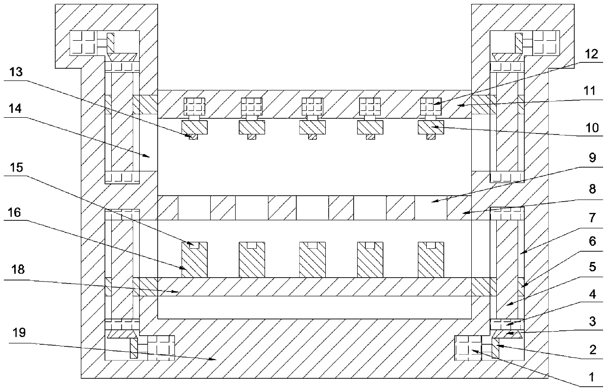
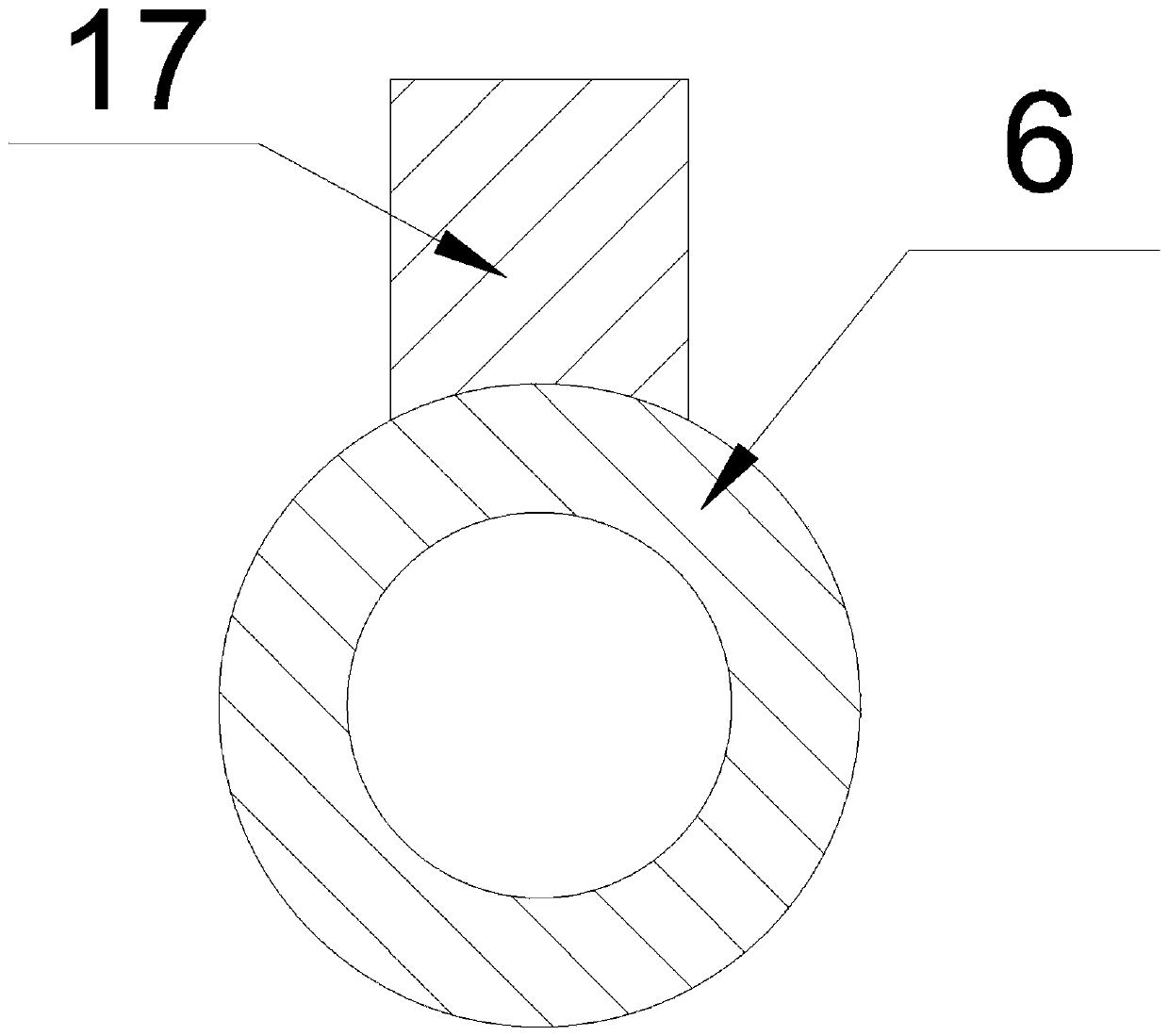
[0030] see figure 1 , figure 2 , a hole grinding device, comprising a concave frame 19, a first workbench 8 with a through hole 9 is provided between the two longitudinal parts of the concave frame 19, and a concave machine is arranged below the first workbench 8. The second workbench 18 that is slidably matched to the two longitudinal parts of the frame 19, the upper surface of the second workbench 18 is provided with a positioning column 16 that is slidably matched with the through hole 9, and the top of the first workbench 8 is provided with two sides of the concave frame 19. The third workbench 11 with sliding fit in the longitudinal part, the lower surface of the third workbench 11 is rotatably connected with the grinding wheel 10, and the grinding wheel 10, the through hole 9, and the positioning column 16 are on the same axis.
[0031] In the present invention, at first the second workbench 18 and the third workbench 11 are slid to both sides of the first workbench 8,...
Embodiment 2
[0033] see figure 1 , figure 2 , a hole grinding device, comprising a concave frame 19, a first workbench 8 with a through hole 9 is provided between the two longitudinal parts of the concave frame 19, and a concave machine is arranged below the first workbench 8. The second workbench 18 that is slidably matched to the two longitudinal parts of the frame 19, the upper surface of the second workbench 18 is provided with a positioning column 16 that is slidably matched with the through hole 9, and the top of the first workbench 8 is provided with two sides of the concave frame 19. The third workbench 11 with sliding fit in the longitudinal part, the lower surface of the third workbench 11 is rotatably connected with the grinding wheel 10, and the grinding wheel 10, the through hole 9, and the positioning column 16 are on the same axis.
[0034] A plurality of through holes 9 are uniformly provided on the first workbench 8 . By setting a plurality of through holes 9 on the fir...
Embodiment 3
[0038] see figure 1 , figure 2 , a hole grinding device, comprising a concave frame 19, a first workbench 8 with a through hole 9 is provided between the two longitudinal parts of the concave frame 19, and a concave machine is arranged below the first workbench 8. The second workbench 18 that is slidably matched to the two longitudinal parts of the frame 19, the upper surface of the second workbench 18 is provided with a positioning column 16 that is slidably matched with the through hole 9, and the top of the first workbench 8 is provided with two sides of the concave frame 19. The third workbench 11 with sliding fit in the longitudinal part, the lower surface of the third workbench 11 is rotatably connected with the grinding wheel 10, and the grinding wheel 10, the through hole 9, and the positioning column 16 are on the same axis.
[0039] The two longitudinal parts of the second workbench 18 and the concave frame 19, the two longitudinal parts of the third workbench 11 a...
PUM
 Abstract
Description
Claims
Application Information
 - R&D
- Intellectual Property
- Life Sciences
- Materials
- Tech Scout
- Unparalleled Data Quality
- Higher Quality Content
- 60% Fewer Hallucinations
Browse by: Latest US Patents, China's latest patents, Technical Efficacy Thesaurus, Application Domain, Technology Topic, Popular Technical Reports.
© 2025 PatSnap. All rights reserved.Legal|Privacy policy|Modern Slavery Act Transparency Statement|Sitemap|About US| Contact US: help@patsnap.com


