Aero-engine power assisting device

An aero-engine and booster technology, applied in the field of helicopters, can solve problems such as poor endurance of multi-rotor helicopters

Active Publication Date: 2019-02-15
辽宁同心圆科技有限公司
View PDF6 Cites 0 Cited by
  • Summary
  • Abstract
  • Description
  • Claims
  • Application Information

AI Technical Summary

Problems solved by technology

[0006] Based on this, it is necessary to provide an aero-engine booster for the above-mentioned problem of poor endurance of multi-rotor helicopters

Method used


Image

  • Aero-engine power assisting device
  • Aero-engine power assisting device
  • Aero-engine power assisting device

Examples


Embodiment Construction

[0031] In order to better understand the purpose, technical solution and technical effect of the present invention, the present invention will be further explained below in conjunction with the accompanying drawings and embodiments. At the same time, it is stated that the embodiments described below are only used to explain the present invention, and are not intended to limit the present invention.

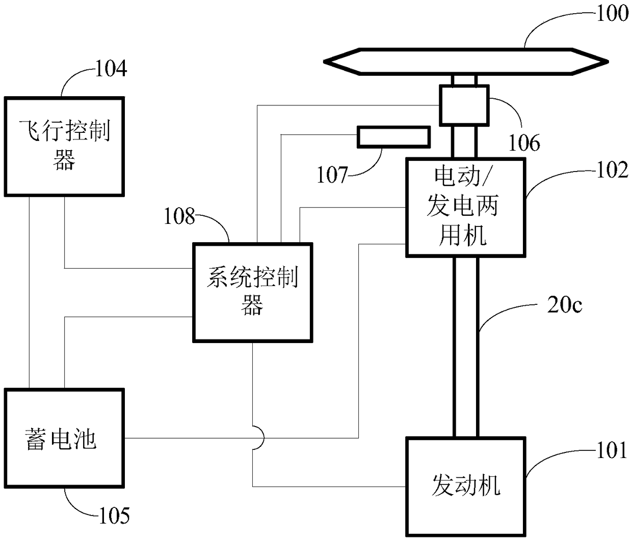
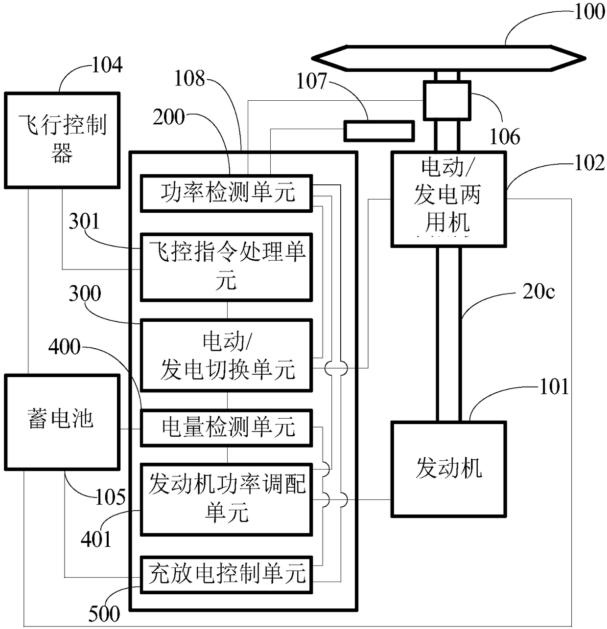
[0032] Please also refer to figure 1 and figure 2 , the aero-engine booster includes: an engine 101, a motor / generator 102 and a propeller 100, the engine 101, an electric / generator 102, and the propeller 100 are coaxially connected, and the engine 101 is used to provide The above-mentioned aeroengine booster device provides total power.

[0033] In one of the embodiments, the engine 101 is also used to provide power for the propeller 100 .

[0034] In one of the embodiments, the engine 101 is also used to provide power for charging the storage battery 105 .

[0035] The moto...


PUM


Abstract

The invention relates to an aero-engine power assisting device. The aero-engine power assisting device comprises an engine, an electric/power generation dual-purpose machine and a propeller which arecoaxially connected; the engine provides total power for the aero-engine power assisting device; the electric/power generation dual-purpose machine sets a nominal voltage according to a take-off nominal voltage program, wherein 1/2 nominal voltage is a reference voltage in an electric power assisting state; if a voltage higher than the 1/2 nominal voltage is applied, the electric/power generationdual-purpose machine is in an electric force boosting state; if a voltage less than the 1/2 nominal voltage is applied, the electric/power generation dual-purpose machine is in an electric force reducing state; if a voltage of zero is applied, the electric/power generation dual-purpose machine is in a power generation state; the output power of the electric/power generation dual-purpose machine isnot higher than 5% of output power of the engine; the aero-engine power assisting device further comprises a torque sensor, a rotation speed measurer, a storage battery and a system controller; the torque sensor and the rotation speed measurer are used for correspondingly detecting torques and rotation speeds of the engine, the electric/power generation dual-purpose machine and the propeller; andthe capacity of the storage battery is not larger than the power consumption of the electric/power generation dual-purpose machine when working for 30 seconds. According to the aero-engine power assisting device, the crash probability is reduced, and the cruising ability is also improved by hundreds of times.

Description

technical field [0001] The invention relates to the technical field of helicopters, in particular to an aeroengine booster. Background technique [0002] The difference between a multi-rotor helicopter and a single-blade helicopter is that the multi-rotor helicopter uses n pairs of propellers to fly, and the attitude balance of each pair of propellers needs to be controlled dynamically. The main blade of a single-blade helicopter is located on the axis of the center of gravity, which is naturally drooped to obtain balance. The pros and cons are: when one propeller fails, the remaining rotors of the multi-rotor helicopter can continue to complete the work of sailing or landing safely, while the single-rotor helicopter is destroyed. Obviously, the practicality of multi-rotor helicopters replacing single-blade helicopters is a technical expectation. [0003] At present, for multi-rotor helicopters driven by fuel engines, due to the working principle of the engine, the engine ...

Claims


Application Information

Patent Timeline
Patent Type & Authority Applications(China)
IPC IPC(8): B64D27/02B64D31/00B64C27/10B64C27/12
CPCB64C27/10B64C27/12B64D27/02B64D31/00Y02T50/60
Inventor 商凯宇周庆党高峰商庆海王景生李明赢
Owner 辽宁同心圆科技有限公司
Why Eureka
Try Eureka