Supercharge Your Innovation With Domain-Expert AI Agents!

Operation control method of unmanned aerial vehicle catapult device using new generation of information technology

A technology of operation control and information technology, which is applied in the field of operation control of UAV projectile devices, can solve the problems of high requirements for the take-off environment, achieve the effect of reducing the dependence on the space environment and facilitating normal take-off

Active Publication Date: 2019-02-15
浙江翔龙航空科技有限公司
View PDF7 Cites 0 Cited by
  • Summary
  • Abstract
  • Description
  • Claims
  • Application Information

AI Technical Summary

Problems solved by technology

[0003] UAVs are generally divided into two types of take-off methods, that is, the vertically ascending rotorcraft and the fixed-wing aircraft that take off by taxiing or gliding. Compared with the rotorcraft, the fixed-wing aircraft has a larger load capacity, and the use of technology is more mature and the flight is more stable. advantages, but its disadvantage is that it needs a long enough runway and has high requirements for the take-off environment. Therefore, for fixed-wing UAVs, the field problem is usually an important factor that limits its popularity.

Method used


Image

  • Operation control method of unmanned aerial vehicle catapult device using new generation of information technology
  • Operation control method of unmanned aerial vehicle catapult device using new generation of information technology
  • Operation control method of unmanned aerial vehicle catapult device using new generation of information technology

Examples


Embodiment

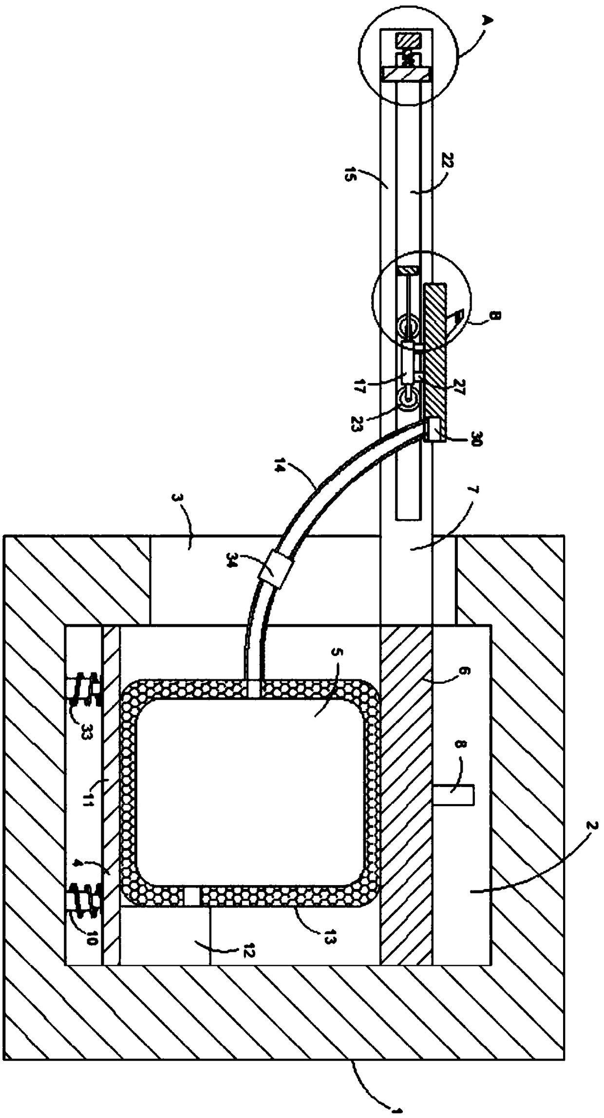
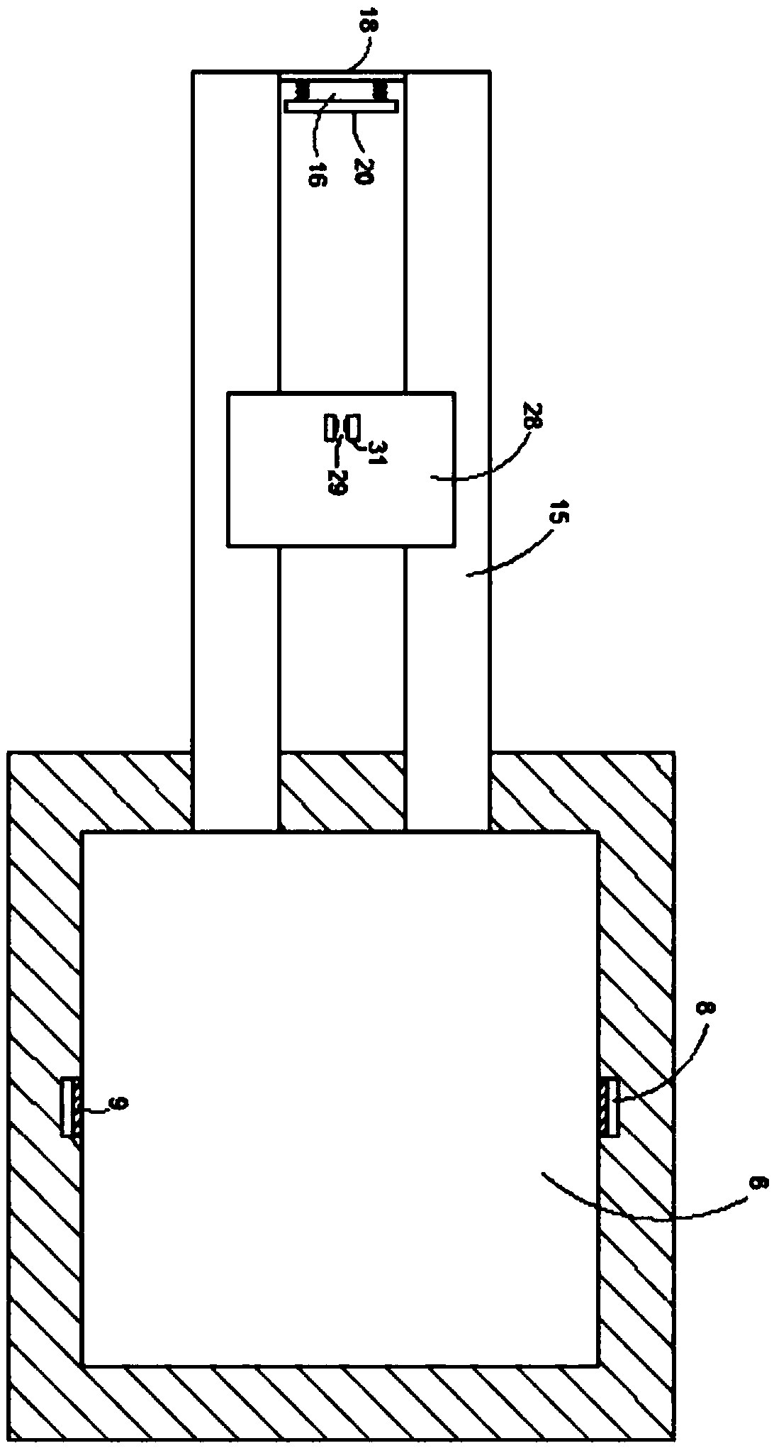
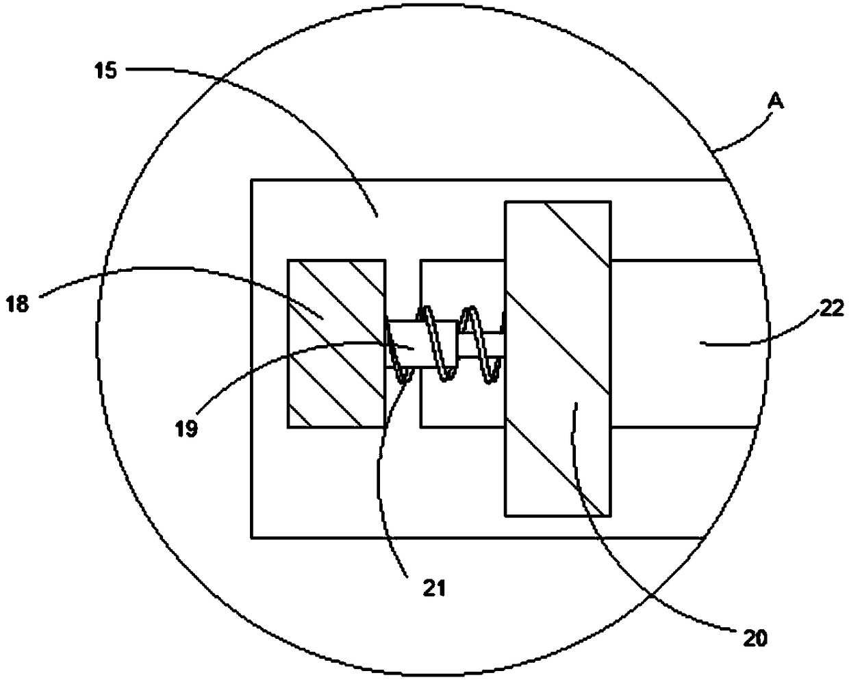
[0030] Such as Figure 1-4 As shown, an operation control method of a UAV projecting device applying a new generation of information technology, wherein the UAV projecting device includes a placement platform 1, a chamber 2 is provided in the placement platform 1, and one end of the chamber 2 The inner wall is vertically provided with two openings 3 communicating with the inside and outside. The bottom of the chamber 2 is fixedly connected with a compression mechanism 4. The compression mechanism 4 includes a plurality of first telescopic rods 10 fixedly connected to the bottom of the chamber 2. The first telescopic rods 10 can protect the first spring 33, the upper ends of multiple first telescopic rods 10 are fixedly connected with the same lifting plate 11, the upper end of the lifting plate 11 is fixedly connected with the lower end of the lifting mechanism 5, and the first telescopic rod 10 is covered with the first A spring 33, the powder cake at the upper and lower ends...


PUM


Abstract

The invention belongs to the technical field of unmanned aerial vehicles and in particular relates to an operation control method of an unmanned aerial vehicle catapult device using a new generation of information technology. The unmanned aerial vehicle catapult device comprises a placing platform; a chamber is formed in the placing platform; two openings whose insides and outsides communicate with each other are vertically formed in the internal wall of one end of the chamber; a compression mechanism is fixedly connected to the bottom of the chamber; a lifting mechanism is fixedly connected to the upper end of the compression mechanism; a movable plate is fixedly connected to the upper end of the lifting mechanism; one end of a sliding mechanism is fixedly connected with one end of the lifting mechanism; the sliding mechanism and the lifting mechanism are arranged in a communication manner; first slide grooves are vertically formed in the internal walls of the front and back ends of the chamber; slide blocks matched with the first slide grooves are arranged in the first slide grooves; the opposite side walls of the two slide blocks are fixedly connected with the side walls of thefront and back ends of the movable plate. The operation control method of the unmanned aerial vehicle catapult device using the new generation of information technology has the advantages that the dependence of a fixed-wing unmanned aerial vehicle on space environments such as a runway can be reduced, and the fixed-wing unmanned aerial vehicle can also be normally used under an environment similarto a rotor unmanned aerial vehicle taking-off environment.

Description

technical field [0001] The invention belongs to the technical field of unmanned aerial vehicles, and in particular relates to an operation control method of an unmanned aerial vehicle projecting device applying a new generation of information technology. Background technique [0002] Unmanned aircraft, referred to as unmanned aerial vehicle, is an unmanned aircraft controlled by radio remote control equipment and self-contained program control device, or is completely or intermittently operated autonomously by on-board computer. With the development of information technology, unmanned It has also begun to gradually use the new generation of information technology to develop a new generation of drone use platform. [0003] UAVs are generally divided into two types of take-off methods, that is, the vertically ascending rotorcraft and the fixed-wing aircraft that take off by taxiing or gliding. Compared with the rotorcraft, the fixed-wing aircraft has a larger load capacity, an...

Claims


Application Information

Patent Timeline
IPC IPC(8): B64F1/04
CPCB64F1/04
Inventor 洪炜林
Owner 浙江翔龙航空科技有限公司
Features
  • R&D
  • Intellectual Property
  • Life Sciences
  • Materials
  • Tech Scout
  • Unparalleled Data Quality
  • Higher Quality Content
  • 60% Fewer Hallucinations
Learn More