
Feeding and discharging device for automatic wire welding machine for light emitting diode production

A light-emitting diode and automatic welding technology, which is applied to auxiliary devices, conveyors, welding equipment, etc., can solve the problems of inconvenient control of diode feeding and discharging, irregular feeding, and low processing efficiency, and achieve simple structure, neat feeding, The effect of improving processing efficiency

Inactive Publication Date: 2019-02-15
阜阳市天颍光电科技有限公司
View PDF0 Cites 2 Cited by
  • Summary
  • Abstract
  • Description
  • Claims
  • Application Information

AI Technical Summary

Problems solved by technology

[0002] Light-emitting diodes are referred to as LEDs for short. When electrons and holes recombine, they can radiate visible light, so they can be used to make light-emitting diodes, which can be used as indicator lights in circuits and instruments, or to form text or digital displays. In general, it is necessary to use an automatic soldering machine for soldering work, but it is inconvenient to control the feeding and discharging of diodes, resulting in low processing efficiency, and at the same time, the feeding is not neat, prone to welding deviation, etc., and the quality is poor

Method used


Image

  • Feeding and discharging device for automatic wire welding machine for light emitting diode production
  • Feeding and discharging device for automatic wire welding machine for light emitting diode production
  • Feeding and discharging device for automatic wire welding machine for light emitting diode production

Examples


Embodiment Construction

[0014] The following will clearly and completely describe the technical solutions in the embodiments of the present invention with reference to the accompanying drawings in the embodiments of the present invention. Obviously, the described embodiments are only some, not all, embodiments of the present invention. Based on the embodiments of the present invention, all other embodiments obtained by persons of ordinary skill in the art without making creative efforts belong to the protection scope of the present invention.

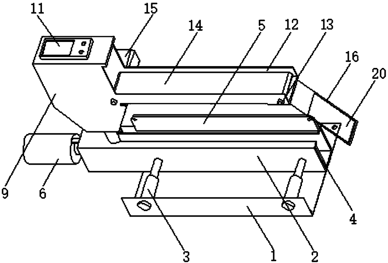
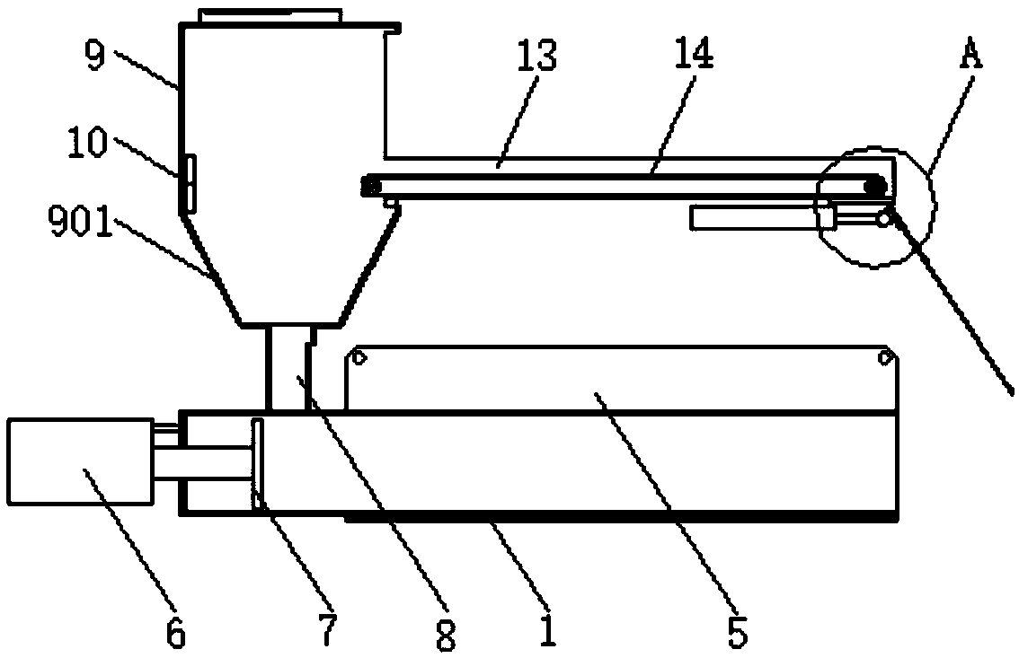
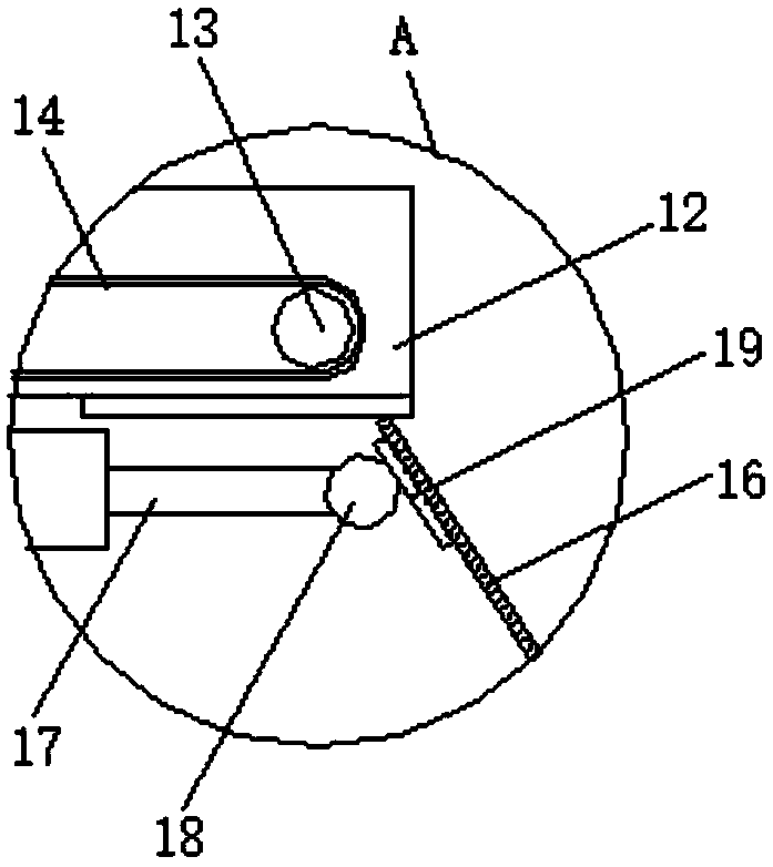
[0015] see Figure 1-3 , the present invention provides a technical solution: a feed-in and discharge device for an automatic wire bonding machine for light-emitting diode production, including a base 1, a clamping box 2 is fixed on the upper surface of the base 1, and a material seam is provided on the upper surface of the clamping box 2 , the front side of the base 1 is fixed with a first electric telescopic rod 3, and the middle part of the clamping box 2 i...


PUM


Abstract

The invention discloses a feeding and discharging device for an automatic wire welding machine for light emitting diode production. The feeding and discharging device for the automatic wire welding machine for light emitting diode production comprises a base, wherein a material clamping box is fixed to the upper surface of the base; a material seam is arranged on the upper surface of the materialclamping box; a first electric telescopic rod is fixed to the front side of the base; and a clamping plate with the same direction as the material clamping box is arranged in the middle of the material clamping box. The feeding and discharging device for the automatic wire welding machine for light emitting diode production is simple in structure and convenient to use; through a charging barrel and a blanking pipe, light emitting diode pins are upwards fallen into the material clamping box, so that light emitting diodes are fed in order; the automatic wire welding machine is conveniently matched for welding tins, and the multiple light emitting diodes can be wire-welded at one time, so that the processing efficiency is improved; through a clamping plate and a push plate, the light emittingdiodes are clamped and fed, so that the stability is high; and the light emitting diodes can be stably sent out through a material guiding plate, so that pin collision and extrusion deformation are avoided, and the processing quality is ensured.

Description

technical field [0001] The invention relates to the technical field of diode processing, in particular to a material feeding and discharging device for an automatic wire bonding machine used in the production of light-emitting diodes. Background technique [0002] Light-emitting diodes are referred to as LEDs for short. When electrons and holes recombine, they can radiate visible light, so they can be used to make light-emitting diodes, which can be used as indicator lights in circuits and instruments, or to form text or digital displays. In general, it is necessary to use an automatic soldering machine for soldering work, but it is inconvenient to control the feeding and discharging of diodes, resulting in low processing efficiency, and at the same time, the feeding is not neat, prone to welding deviation, etc. Contents of the invention [0003] The technical problem to be solved by the present invention is to overcome the existing defects and provide a material feeding a...

Claims


Application Information

Patent Timeline
Patent Type & Authority Applications(China)
IPC IPC(8): B65G47/82B23K3/08
CPCB65G47/82B23K3/08B65G2203/0241
Inventor 魏玲
Owner 阜阳市天颍光电科技有限公司
Learn More