
A solid-liquid separation device and septic tank with self-cleaning function

A technology of solid-liquid separation and septic tank, which is applied in the direction of biological sludge treatment, etc., and can solve problems such as easy blockage

Active Publication Date: 2021-07-06
XI'AN UNIVERSITY OF ARCHITECTURE AND TECHNOLOGY
View PDF0 Cites 0 Cited by
  • Summary
  • Abstract
  • Description
  • Claims
  • Application Information

AI Technical Summary

Problems solved by technology

[0006] The purpose of the present invention is to provide a solid-liquid separation device and a septic tank with self-cleaning function, to solve the problems of the solid-liquid separation device in the septic tank in the prior art, such as easy blockage after long-term use

Method used


Image

  • A solid-liquid separation device and septic tank with self-cleaning function
  • A solid-liquid separation device and septic tank with self-cleaning function
  • A solid-liquid separation device and septic tank with self-cleaning function

Examples


Embodiment 1

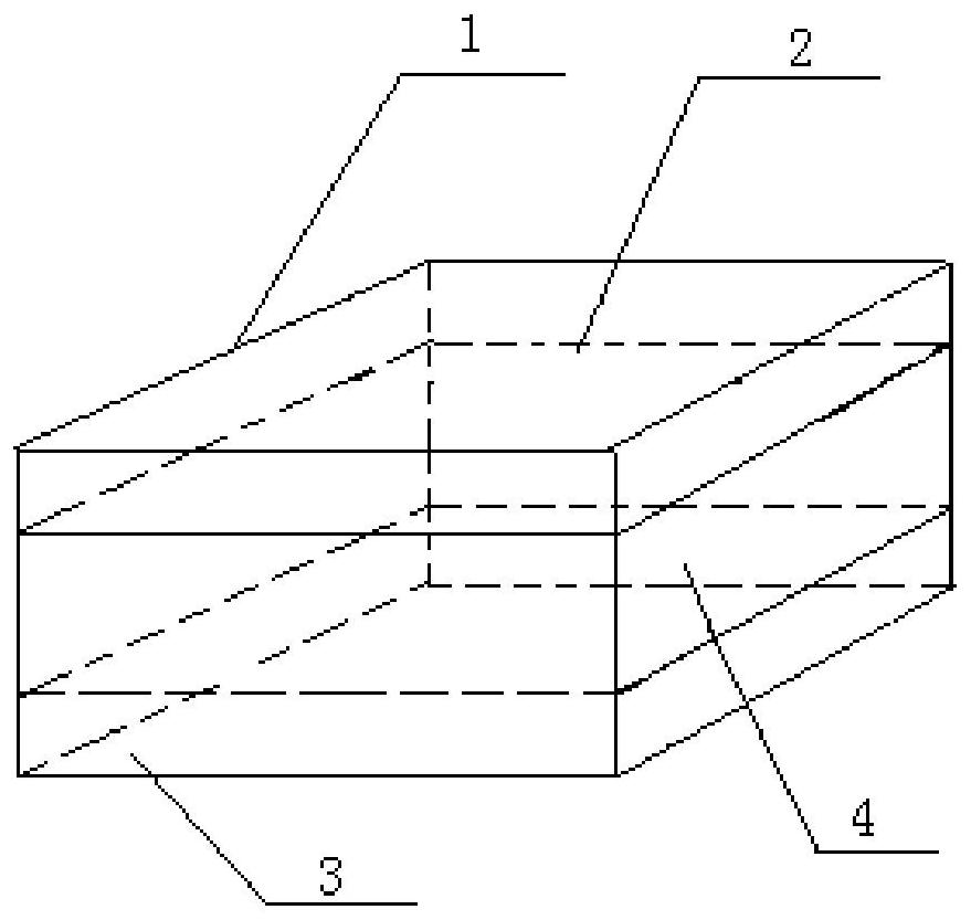
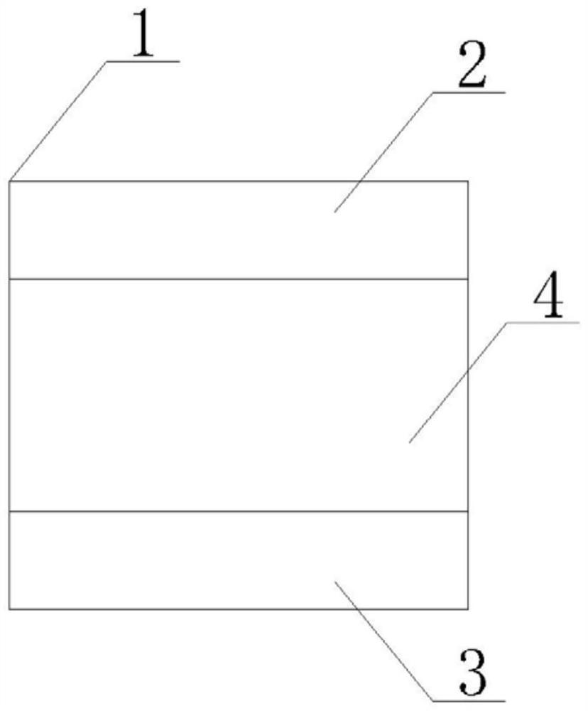
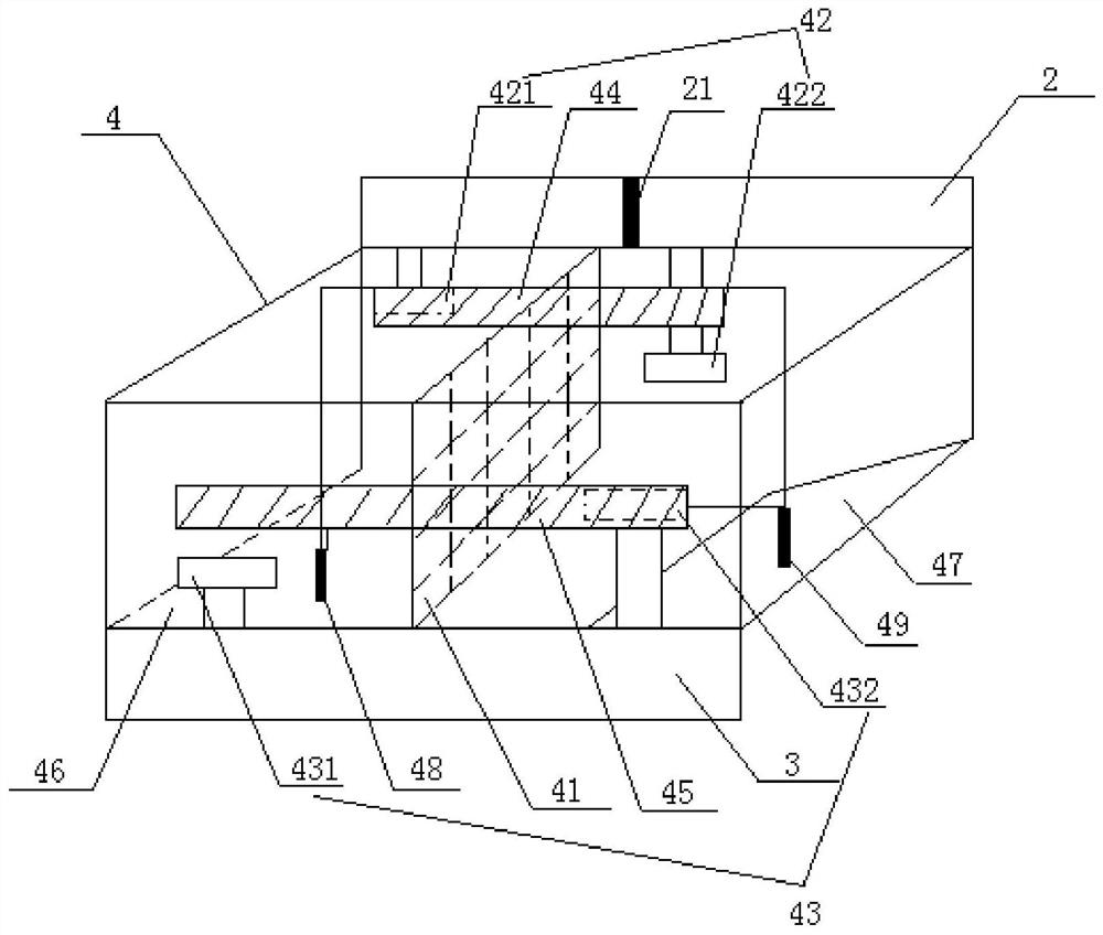
[0043] In this embodiment, a solid-liquid separation device with self-cleaning function is disclosed, which includes a device body 1, and a water inlet channel 2 and a water outlet channel 3 are respectively arranged on a pair of side walls of the device body 1. The device body 1 is provided with a separation space 4, and a partition 41 is arranged inside the separation space 4, and a pair of water inlets 42 are arranged on the side walls of the separation space 4, and the pair of water inlets 42 They are respectively located on both sides of the partition 41; a pair of water outlets 43 are also provided on the side wall of the separation space 4, and the pair of water outlets 43 are respectively located on both sides of the partition 41; The water inlet 42 communicates with the water inlet channel 2, and the water outlet 43 communicates with the water outlet channel 3;

[0044] A first baffle plate 44 and a second baffle plate 45 are also provided on the side wall of the sepa...

Embodiment 2

[0075] In this embodiment, a solid-liquid separation septic tank with self-cleaning function is disclosed, including a septic tank body A, and a water inlet pipe B and an outlet pipe C are arranged on the side wall of the septic tank body A, A solid-liquid separation device D as described in Embodiment 1 is also installed inside the septic tank body A, the water inlet channel 2 of the solid-liquid separation device communicates with the water inlet pipe B, and the water outlet The channel 3 communicates with the outlet pipe C.

[0076] Such as Figure 10-11 As shown, the solid-liquid separation septic tank in this embodiment includes the septic tank body A, the solid-liquid separation device D described in Embodiment 1, and the solid-liquid separation device D is installed inside the septic tank body A As a preferred embodiment, the solid-liquid separation device D is installed on the top and left sides of the septic tank body A.

[0077] The water inlet channel 2 of the sol...


PUM


Abstract

The invention discloses a solid-liquid separation device with self-cleaning function and a septic tank, comprising a separation space, a partition net is arranged inside the separation space, a pair of water inlets are arranged on the side wall of the separation space, a pair of water inlets They are respectively located on both sides of the partition net; a pair of water outlets are also provided on the side wall of the separation space, and the pair of water outlets are respectively located on both sides of the partition net; a second water outlet is also provided on the side wall of the separation space. A baffle plate and a second baffle plate, the first baffle plate is movably installed on the water inlet side of the water inlet, and the second baffle plate is movably installed on the water outlet side of the water outlet; the solid-liquid provided by the invention The separation device changes the flow direction of the sewage in and out of the separation space back and forth, and scours the dirt attached to the separation net to achieve the effect of self-cleaning.

Description

technical field [0001] The invention relates to a solid-liquid separation device and a septic tank, in particular to a solid-liquid separation device and a septic tank with a self-cleaning function. Background technique [0002] A septic tank is a small unit facility for effective local treatment of domestic sewage. It is a primary transitional domestic sewage treatment structure and is mainly used to temporarily store excrement and domestic sewage that have not been discharged into the municipal pipe network, thereby slowing down the drainage system. drainage pressure. [0003] Septic tanks use the principles of sedimentation and anaerobic fermentation to remove suspended organic matter in domestic sewage. Domestic sewage is divided into gray water and black water. Black water refers to toilet fecal sewage, including human urine and feces. Gray water refers to sewage from household kitchens, laundry and bathing. Black water contains most of the organic loads and pathogens...

Claims


Application Information

Patent Timeline
Patent Type & Authority Patents(China)
IPC IPC(8): C02F11/04
CPCC02F11/04
Inventor 卢金锁王晓祎周亚鹏陈军廖邦友陈尚宋光顺
Owner XI'AN UNIVERSITY OF ARCHITECTURE AND TECHNOLOGY
Learn More