Frame-shear wall structure formwork system and construction method thereof

A technology of formwork system and frame-shear structure, which is applied in the field of concrete construction, can solve the problems of difficult demoulding, complex construction of wooden formwork, and less number of times a single wooden formwork can be used.

Inactive Publication Date: 2019-02-15
HANGZHOU JIANGRUN TECH LIMITED
View PDF0 Cites 1 Cited by
  • Summary
  • Abstract
  • Description
  • Claims
  • Application Information

AI Technical Summary

Problems solved by technology

However, the construction of wooden formwork is more complicated and takes a lot of time, including processing time, formwork erection is slow
Secondly, the number of times a single wooden formwork can be used is small, and a large number of waste wooden formwor

Method used


Image

  • Frame-shear wall structure formwork system and construction method thereof
  • Frame-shear wall structure formwork system and construction method thereof
  • Frame-shear wall structure formwork system and construction method thereof

Examples


Embodiment

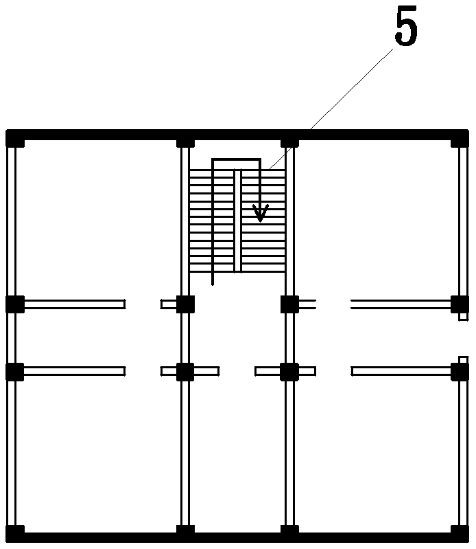
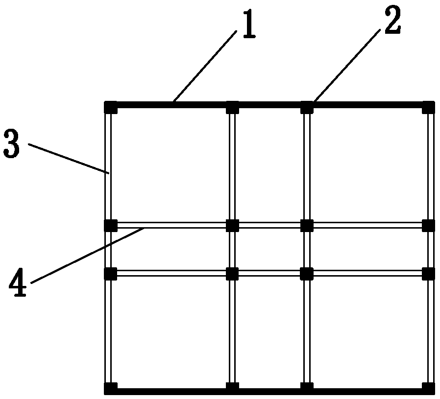
[0072] Example: such as Figure 1-2 As shown, the formwork system of the frame-shear structure includes symmetrically arranged shear walls 1, and the relatively symmetrical shear walls 1 are connected by several beams 3. Columns 2 are arranged at the joints between the shear walls 1 and the beams 3, and several beams 3 are vertically connected to each other. There are longitudinal beams 4, columns 2 are arranged at the connection between the beams 3 and the longitudinal beams 4, and a staircase 5 is arranged between the shear wall 1, the longitudinal beams 4 and the two beams 3 in the middle; the shear wall 1 includes the shear wall stereotypes The column 2 includes a shaped template for the frame column; the beam 3 and the longitudinal beam 4 include a shaped template for the frame beam; the staircase 5 includes a shaped template for the staircase.

[0073] The finalized formwork for the shear wall, the finalized formwork for the frame column, the finalized template for the f...

specific Embodiment approach

[0097] The specific embodiment of the present invention comprises the following steps:

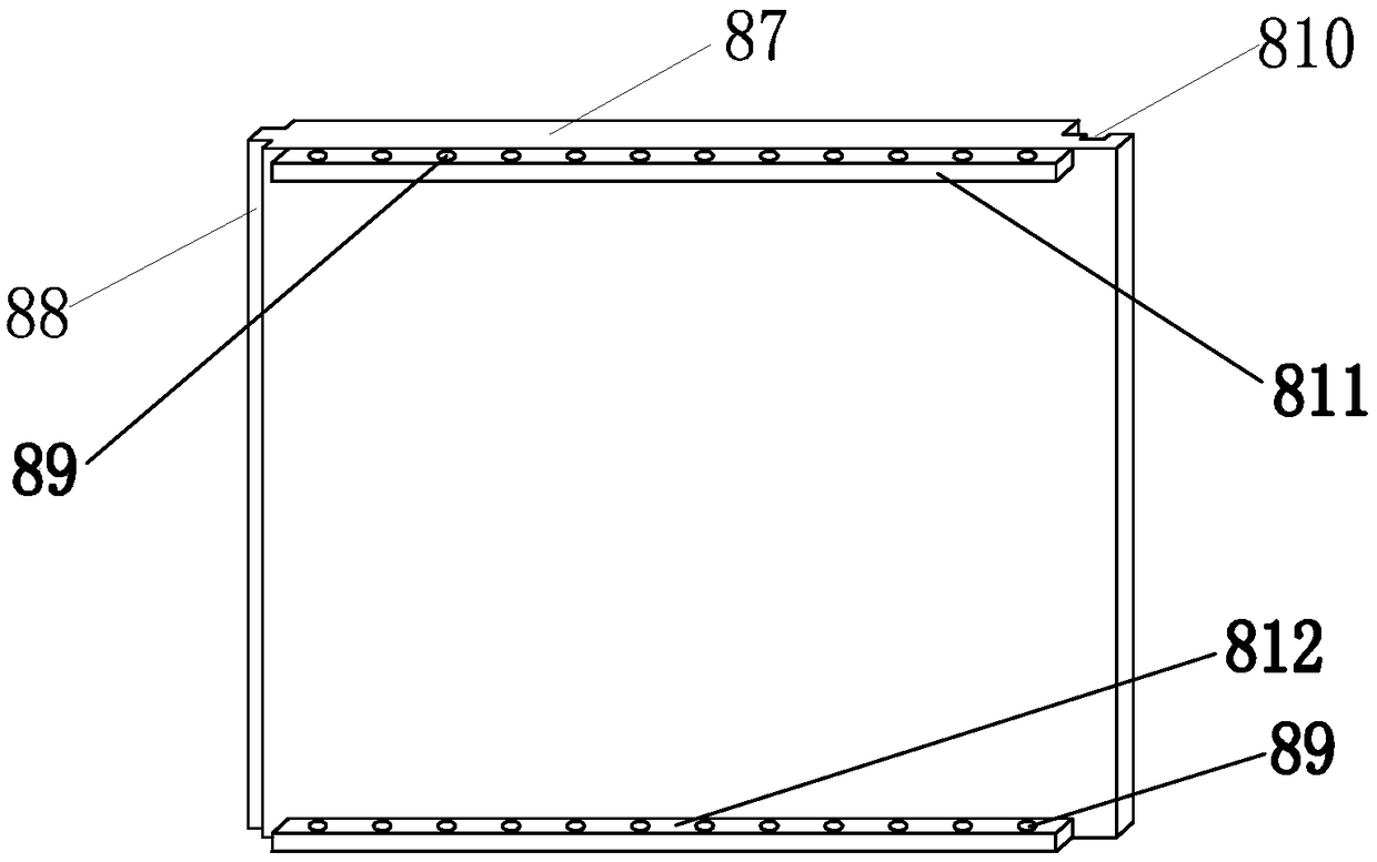
[0098] Step 1, splicing the side formwork, splicing the two beam side formworks left and right, and the bolt holes on the connecting plate must be strictly aligned. Then pass the screws through the two aligned bolt holes, and fix them with nuts, so that the two adjacent side forms are connected together.

[0099] Step 2, Bottom template splicing; there is a bottom connection bump on the side template, place the bottom template on the rear of the bump, make the bolt holes on the bottom template align with the bolt holes on the bump on the side template, and then use Drill the bolt into the hole, because the hole does not penetrate, so it needs to be screwed in with the threaded bolt to fix it, and then insert another bottom template on the protrusion of the bottom template, so that the groove on the bottom template Insert into the bump to splice the two templates together, and then splice ...


PUM


Abstract

The invention relates to a frame-shear wall structure formwork system and a construction method thereof. The frame-shear wall structure formwork system comprises symmetrically arranged shear walls which are connected through a plurality of crossbeams, stand columns are arranged at the joint of the shear walls and the crossbeams, longitudinal beams are vertically connected to the crossbeams, standcolumns are arranged at the joint of the crossbeams and longitudinal beams, and stairs are arranged between the shear walls, the longitudinal beams and the two crossbeams located in the middle. The shear walls comprises shear wall shaping formworks. The stand columns comprise frame column shaping formworks. The crossbeams and the longitudinal beams comprise frame beam shaping formworks. The stairscomprise stair shaping formworks. According to the frame-shear wall structure formwork system and the construction method thereof, step splicing holes and stair bottom plate connecting holes are formed in stair prefabricated side formworks; and only stair bottom plate modules and connecting pieces on step formworks need to be inserted into corresponding reserved holes in sequence in the stair formwork erection process, and then the stair bottom plate modules and the connecting pieces on the step formworks are fixed by screws and nuts, so that the frame-shear wall structure formwork system isquickly completed.

Description

technical field [0001] The invention relates to the technical field of concrete buildings, in particular to a frame-shear structure formwork system and a construction method. Background technique [0002] Frame-shear wall structure is also called frame-shear structure. This structure is to arrange a certain number of shear walls in the frame structure. This kind of shear wall is called frame shear wall. They form a flexible and free use space to meet It meets the requirements of different building functions, and at the same time has enough shear walls and considerable rigidity. [0003] At present, most of the formwork systems used in the frame-shear wall structure are wood formwork, because the wood formwork is easy to process on the construction site, and can be processed and formed according to the geometric shape of the specific components of the frame-shear wall structure. The outline of the component is drawn on the template, and then the cutting machine can cut it al...

Claims


Application Information

Patent Timeline
IPC IPC(8): E04G11/02E04G13/00
CPCE04G11/02E04G13/00
Inventor 王新泉
Owner HANGZHOU JIANGRUN TECH LIMITED
Why Eureka
Try Eureka