Cooling control system of underground continuous wall cutting equipment and cutting equipment

A technology of underground diaphragm wall and cutting equipment, which is applied in the direction of mechanical equipment, fluid pressure actuation system testing, fluid pressure actuation system components, etc. It can solve the problems of waste of resources, high energy consumption of cooling hydraulic system, and low reliability. Achieve the effect of avoiding resource waste, reducing failure rate and improving reliability

Active Publication Date: 2019-02-15
CHINA RAILWAY CONSTR HEAVY IND
View PDF7 Cites 1 Cited by
  • Summary
  • Abstract
  • Description
  • Claims
  • Application Information

AI Technical Summary

Problems solved by technology

The existing cooling hydraulic system usually includes a cooling device and a driving oil circuit for driving the cooling device. The existing driving oil circuit is usually driven by a single hydraulic pump, which makes the cooling hydraulic system work in a single mode and cannot follow the main hydraulic pressure. The oil temperature of the system is adjusted, the reliability is relatively low, and the drive oil supply to the cooling device cannot be fully utilized, which causes waste of resources to a certain extent, resulting in relatively high energy consumption
[0004] Therefore, the existing cooling hydraulic system has high energy consumption and low reliability

Method used


Image

  • Cooling control system of underground continuous wall cutting equipment and cutting equipment

Examples


Embodiment Construction

[0041] The following will clearly and completely describe the technical solutions in the embodiments of the present invention with reference to the accompanying drawings in the embodiments of the present invention. Obviously, the described embodiments are only some, not all, embodiments of the present invention. Based on the embodiments of the present invention, all other embodiments obtained by persons of ordinary skill in the art without making creative efforts belong to the protection scope of the present invention.

[0042] In order to enable those skilled in the art to better understand the solution of the present invention, the present invention will be further described in detail below in conjunction with the accompanying drawings and specific embodiments.

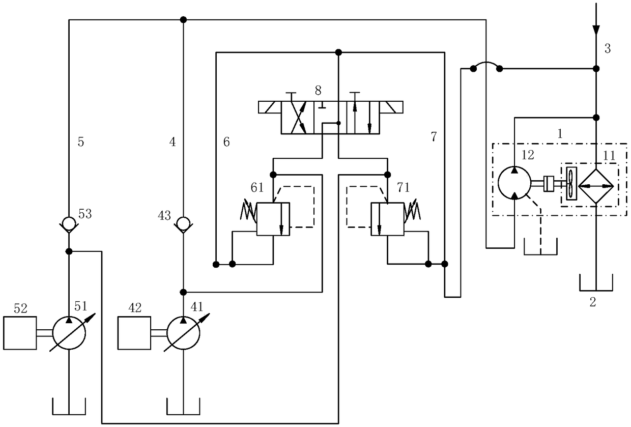
[0043] Please refer to figure 1 , figure 1 It is a hydraulic principle diagram of the cooling control system of the underground diaphragm wall cutting equipment provided by a specific embodiment of the present inve...


PUM


Abstract

The invention discloses a cooling control system of underground continuous wall cutting equipment. The cooling control system comprises a work oil path with a cooling device, a first drive oil path, asecond drive oil path, a first protection oil path, a second protection oil path and a reversing valve; the first drive oil path and the second drive oil path are used for driving the cooling device,the first protection oil path and the second protection oil path are used for correspondingly protecting the first drive oil path and the second drive oil path, an inlet of the reversing valve is connected with an inlet of the first protection oil path and an inlet of the second protection oil path, and an outlet of the reversing valve is connected with the work oil path. The first drive oil pathand the second drive oil path can select the proper work flow according to the temperature of the work oil path, resource waste caused by the fact that the cooling device excessively supplies high-pressure oil can be avoided, the reversing valve can effectively avoid overspeeding of the cooling device, the drive oil paths are increased, the failure rate of the cooling device is reduced, and therefore the cooling control system of the underground continuous wall cutting equipment is low in energy consumption and high in reliability. The invention further provides the cutting equipment including the cooling control system.

Description

technical field [0001] The invention relates to the technical field of underground diaphragm walls, in particular to a cooling control system for underground diaphragm wall cutting equipment. The invention also relates to a cutting device. Background technique [0002] First, excavate a long and narrow deep groove along the peripheral axis of the deep excavation project under the condition of mud retaining wall, then hang the steel cage into the groove after clearing the deep groove, and finally pour concrete into the steel cage by the conduit method, so that An underground continuous wall is formed. In view of the advantages of high rigidity and strong soil bearing capacity of underground diaphragm walls, underground diaphragm walls are commonly used to achieve functions such as water interception and anti-seepage, especially in urban anti-seepage projects. [0003] The underground diaphragm wall cutting equipment used to excavate the underground diaphragm wall requires a...

Claims


Application Information

Patent Timeline
Patent Type & Authority Applications(China)
IPC IPC(8): F15B21/0423F15B19/00F15B11/08
CPCF15B11/08F15B19/00F15B21/04
Inventor 刘飞香郑大桥肖前龙曾庆峰李晓星张廷寿张玉良刘伟
Owner CHINA RAILWAY CONSTR HEAVY IND
Why Eureka
Try Eureka