Flow regulating valve element
A flow control valve and flow control technology, applied in sliding valves, valve devices, engine components, etc., can solve the problems of complex valve core structure, inconvenient use, waste of water resources, etc., to avoid wasting water resources, easy to operate, The effect of low production cost
- Summary
- Abstract
- Description
- Claims
- Application Information
AI Technical Summary
Problems solved by technology
Method used
Image
Examples
Embodiment 1
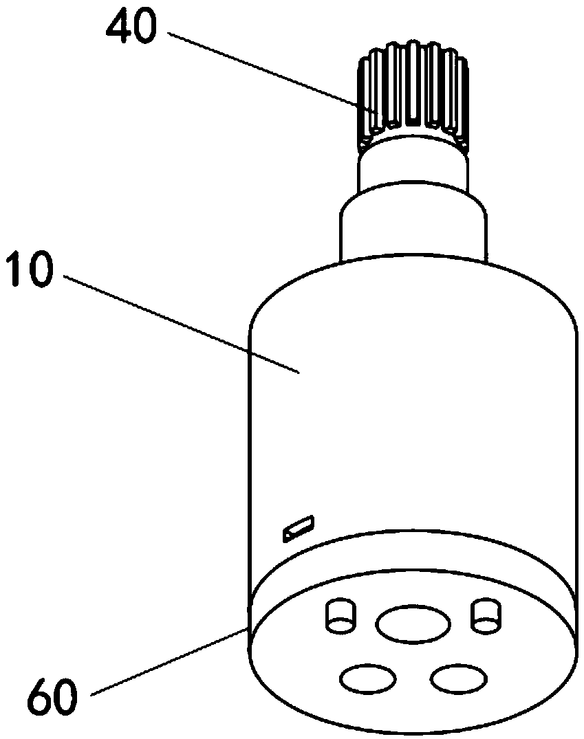
[0051] Such as Figure 4-7 As shown, the fixed valve plate 20 is fixedly arranged on the bottom of the housing 10 through the base 60, and the fixed valve plate 20 is provided with three water outlets 21, wherein the first water outlet 211 and the second water outlet 212 are water inlets, respectively used for For the input of cold water and hot water, the third water outlet 213 is a water outlet, which is used for the water source to output from the valve core; the base 60 is provided with a water outlet 61 corresponding to the water outlet 21 on the fixed valve plate 20 one by one. The sheet 30 is provided with a through-hole-shaped water passage 31; wherein the third water outlet 213 communicates with the water passage 31, the overlapping area of the first water outlet 211 and the water passage 31, the second water outlet 212 and the water passage. The overlapping area of the channel 31 changes with the rotation angle of the movable valve plate 30 relative to the fixed ...
Embodiment 2
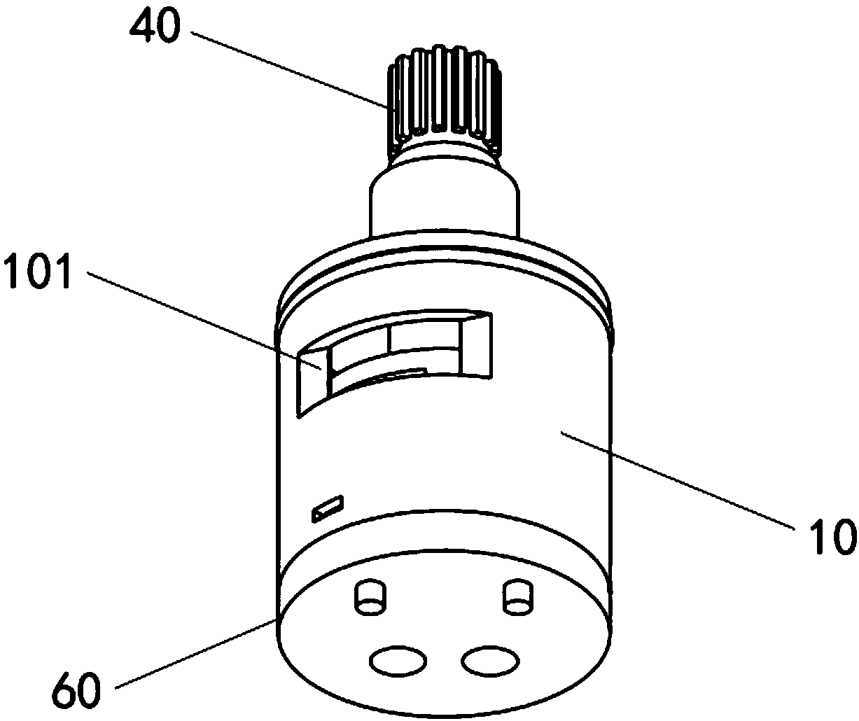
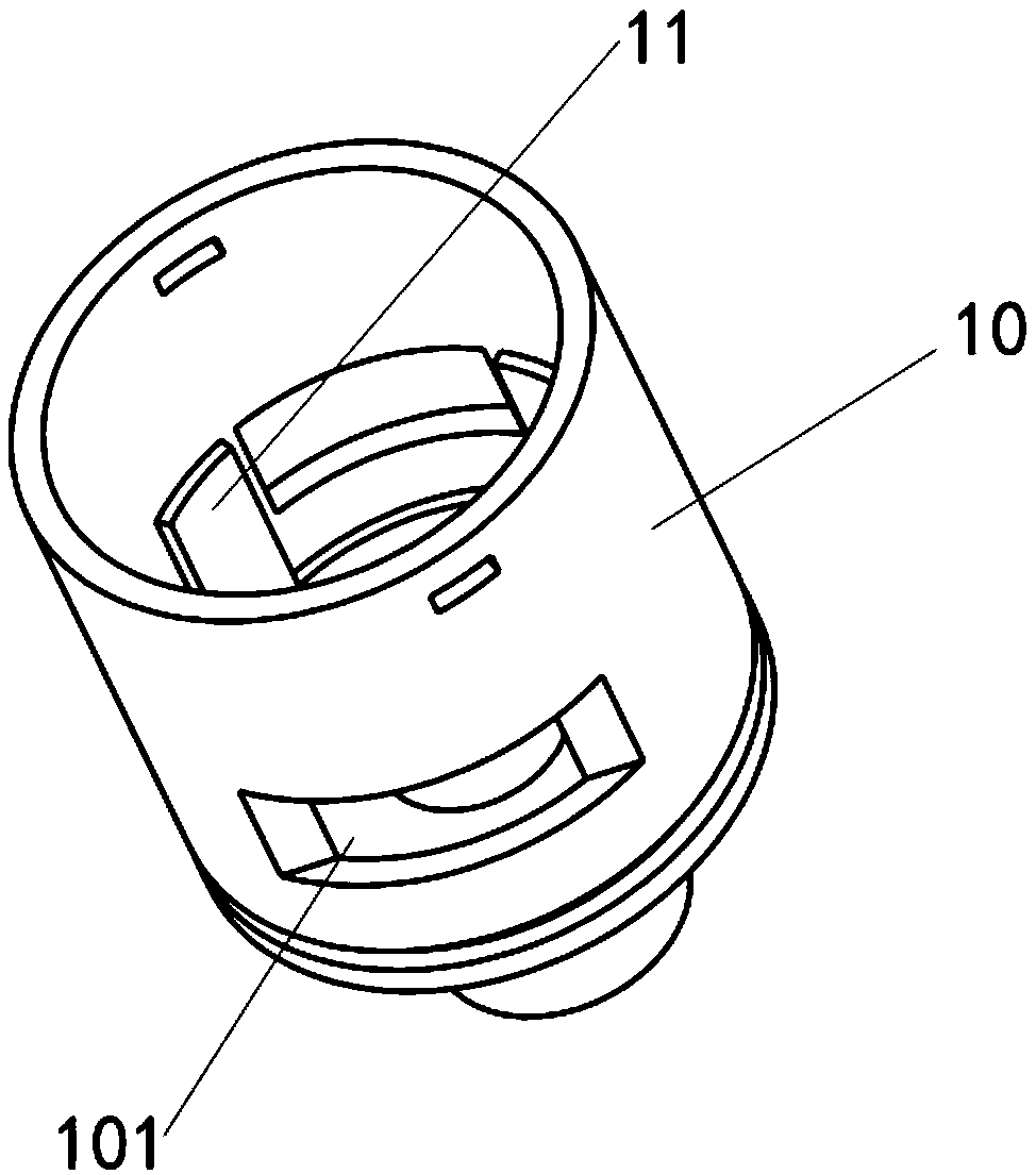
[0059] Such as Figure 8-10 As shown, the fixed valve plate 20 is fixedly arranged on the bottom of the housing 10 through the base 60, and the fixed valve plate 20 is provided with two water outlets 21, wherein the first water outlet 211 and the second water outlet 212 are water inlets, respectively. For the input of cold water and hot water, the base 60 is provided with a water outlet 61 corresponding to the water outlet 21 on the fixed valve plate 20, and a water outlet 101 is provided on the side wall of the housing 10 for the water source to flow from the valve core. Output: On the movable valve plate 30, there is a water passage 31 with a trumpet-shaped through hole, and the opening shape of the end of the water passage 31 facing the fixed valve plate 20 is non-circular; wherein the water outlet 101 passes through the inside of the housing 10 The cavity is connected with the opening of the water passage 31 located on the upper surface of the movable valve plate 30, the o...
Embodiment 3
[0067] Such as Figure 11-14 As shown, the fixed valve plate 20 is fixedly arranged on the bottom of the housing 10 through the base 60, and the fixed valve plate 20 is provided with two water outlets 21, wherein the first water outlet 211 and the second water outlet 212 are water inlets, respectively. For the input of cold water and hot water, the base 60 is provided with a water outlet 61 corresponding to the water outlet 21 on the fixed valve plate 20, and a water outlet 101 is provided on the side wall of the housing 10 for the output of water flow; A semi-closed notch-shaped water passage 31 is provided on the movable valve plate 30; the water outlet 101 communicates with the water passage 31 through the cavity inside the housing 10, and the overlap between the first water passage 211 and the water passage 31 Area, the overlapping area of the second water outlet 212 and the water passage 31 changes with the rotation angle of the movable valve plate 30 relative to the fi...
PUM
 Abstract
Description
Claims
Application Information
 - R&D
- Intellectual Property
- Life Sciences
- Materials
- Tech Scout
- Unparalleled Data Quality
- Higher Quality Content
- 60% Fewer Hallucinations
Browse by: Latest US Patents, China's latest patents, Technical Efficacy Thesaurus, Application Domain, Technology Topic, Popular Technical Reports.
© 2025 PatSnap. All rights reserved.Legal|Privacy policy|Modern Slavery Act Transparency Statement|Sitemap|About US| Contact US: help@patsnap.com


