
Dual-phase variable electromagnetic heat storage device and use method thereof

An electromagnetic heating device and heat storage device technology, applied in heating methods, electric heating systems, applications, etc., can solve problems such as large heat loss, time imbalance, and increased use costs, and achieve high heat transfer efficiency and prolong heat release time , the effect of high practical value

Pending Publication Date: 2019-02-15
赵春雷
View PDF10 Cites 0 Cited by
  • Summary
  • Abstract
  • Description
  • Claims
  • Application Information

AI Technical Summary

Problems solved by technology

[0002] In recent years, China's requirements for environmental protection have become higher and higher, and people's awareness of environmental protection is also gradually strengthening. In order to find blue sky and white clouds and return to green water and green mountains, people have proposed various environmental protection plans; among them, Hebei and other areas around Beijing have proposed coal mines. The heating scheme of changing to electricity, that is, the scheme of heating with electric energy instead of the traditional scheme of burning coal for heating. After the large-scale implementation of this scheme, it will definitely be able to greatly reduce CO2. 2 , SO 2 discharge of pollutants such as pollutants, but China's electric energy is not particularly abundant, and not only is it unevenly distributed geographically, but also unevenly in time. There are peaks and troughs in electricity consumption every day. Power resources are in short supply, and power resources are in surplus when power consumption is low. For this reason, relevant departments have formulated different market prices for power in different periods of time, hoping to alleviate the pressure of peak and valley electricity through market regulation. In fact, it has indeed played a good role. effect; but for winter heating, even if consciously reducing the amount of electricity used during peak hours, it is still inevitable to carry out necessary heating work during peak hours, which not only adds trouble to the national power pool, but also improves The economic burden of users, for this reason, there is an urgent need for a device that can use electric energy to generate heat and store energy. It can use electric energy to generate heat at night and other low-peak electricity consumption / valley electricity, and store the heat. During the day and other peak electricity consumption The stored heat will be dissipated during hour / peak power to heat the room
[0003] Although there are some heat storage and energy storage devices in the prior art, there are many problems in the actual use process, such as low heat storage capacity. In order to meet a certain amount of heat energy storage, the equipment needs to be made extremely large, which limits the use site, which increases the cost of use, and the temperature of the storage wall of some equipment is too high, which is likely to cause dangers such as burns; in addition, the structure of the existing heat storage and energy storage equipment is unreasonable, making it low in heat transfer efficiency. The heat loss in the heat transfer process is relatively large; in addition, when the existing heat storage energy storage equipment releases heat during the peak power period, it can only continue to release heat for 5-6 hours. After 5-6 hours, the temperature of the heat storage material will drop sharply Reduced, it no longer has heat dissipation capacity, even if the total amount of heat storage material is increased, it only increases the heat dissipation during the heat dissipation period, and cannot effectively prolong the heat dissipation time

Method used

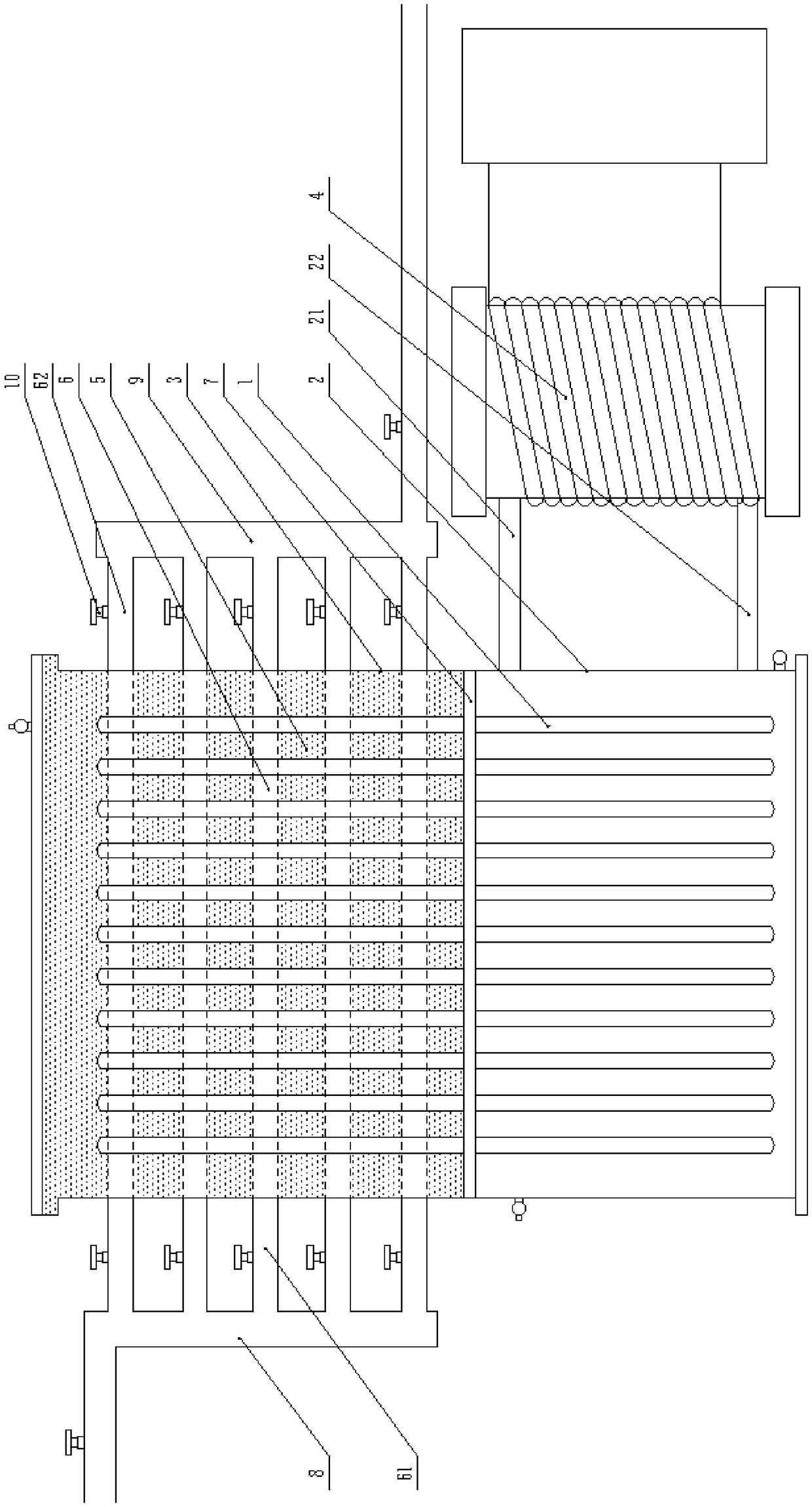
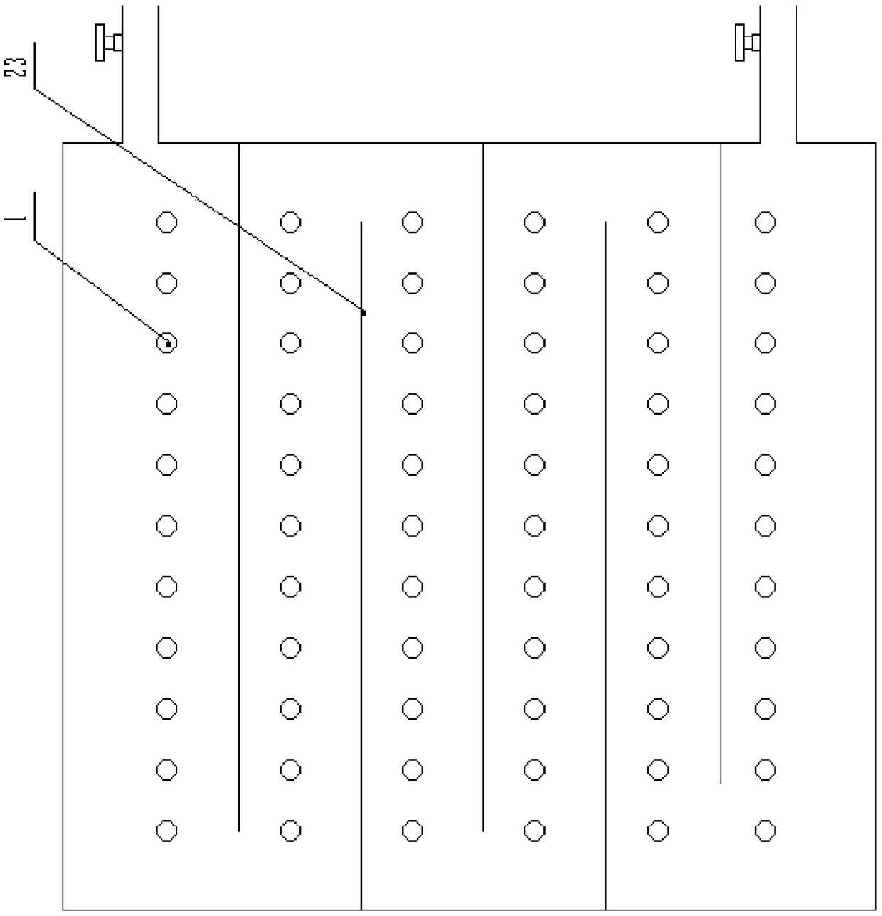
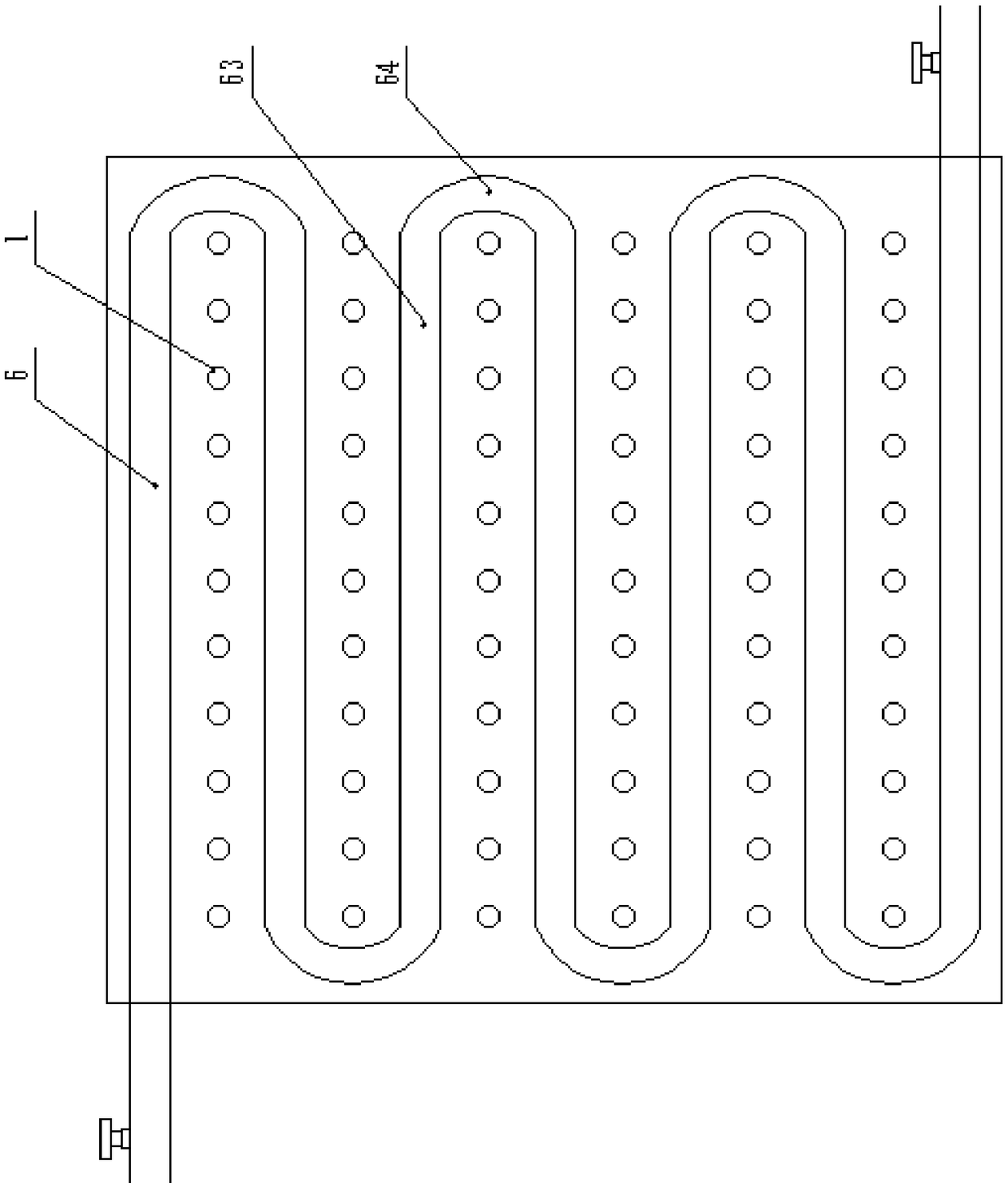

Image

  • Dual-phase variable electromagnetic heat storage device and use method thereof
  • Dual-phase variable electromagnetic heat storage device and use method thereof
  • Dual-phase variable electromagnetic heat storage device and use method thereof

Examples


experiment example

[0128] Use the dual-phase change electromagnetic heat storage device provided by the present invention to store heat for an indoor room of 100 square meters; specifically, heat the water in the primary circuit through the electromagnetic heating device, and transfer the heat to the heating coil and the heating pipe through the heat pipe The phase-change thermal storage filler heats the room through the heating coil, stores heat through the phase-change thermal storage filler, and gradually releases heat during peak power.

[0129] Select one of the consecutive 24 hours to count the temperature and power consumption;

[0130] Continuously heating by electromagnetic heating device for 10 hours during valley electricity, power consumption is 126.5 degrees, and within 24 hours, the total heat provided to the room through the heating coil is 432,000 kJ, so it can be known that the dual-phase change electromagnetic storage battery provided by the application The thermal efficiency o...


PUM


Abstract

The invention discloses a dual-phase variable electromagnetic heat storage device. According to the dual-phase variable electromagnetic heat storage device, the electromagnetic heating manner is usedfor converting electric energy into heat energy, heat energy is stored in water or other media, through a heat pipe with a phase change medium, the heat is conducted to the other seal area, the area is filled with a phase change heat storage material and multiple heat supply coil pipes, the heat supply coil pipes are arranged in a layered manner in the vertical direction, when heat needs to be supplied through the phase change heat storage material, the heat supply coil pipes sequentially work from bottom to top, the heat supply time of the heat storage device is prolonged to the maximum degree, and the device can continuously supply heat in peak electricity time every time.

Description

technical field [0001] The invention relates to the technical field of energy saving and environmental protection, in particular to a dual-phase change electromagnetic heat storage device. Background technique [0002] In recent years, China's requirements for environmental protection have become higher and higher, and people's awareness of environmental protection is also gradually strengthening. In order to find blue sky and white clouds and return to green water and green mountains, people have proposed various environmental protection plans; among them, Hebei and other areas around Beijing have proposed coal mines. The heating scheme of changing to electricity, that is, the scheme of heating with electric energy instead of the traditional scheme of burning coal for heating. After the large-scale implementation of this scheme, it will definitely be able to greatly reduce CO2. 2 , SO 2 discharge of pollutants such as pollutants, but China's electric energy is not particul...

Claims


Application Information

Patent Timeline
Patent Type & Authority Applications(China)
IPC IPC(8): F24D13/04F24D15/02F24D19/10
CPCF24D13/04F24D15/02F24D19/1096
Inventor 赵春雷
Owner 赵春雷
Learn More