Rotor speed monitoring processor

A rotor speed and processor technology, applied to devices using electric/magnetic methods, can solve problems such as inconsistent parameter values, signal load impedance mismatch, and complex wiring on the aircraft, so as to reduce operating costs and maintenance workload. , the effect of improving utilization efficiency

Active Publication Date: 2019-02-15
SHAANXI QIANSHAN AVIONICS
View PDF13 Cites 4 Cited by
  • Summary
  • Abstract
  • Description
  • Claims
  • Application Information

AI Technical Summary

Problems solved by technology

Due to the large number of equipment on the machine to collect the speed signal, the distribution is wide, and the collection and processing methods are differen

Method used


Image

  • Rotor speed monitoring processor
  • Rotor speed monitoring processor
  • Rotor speed monitoring processor

Examples


Embodiment Construction

[0026] Below in conjunction with accompanying drawing, the present invention is described in further detail, please refer to Figure 1 to Figure 3 .

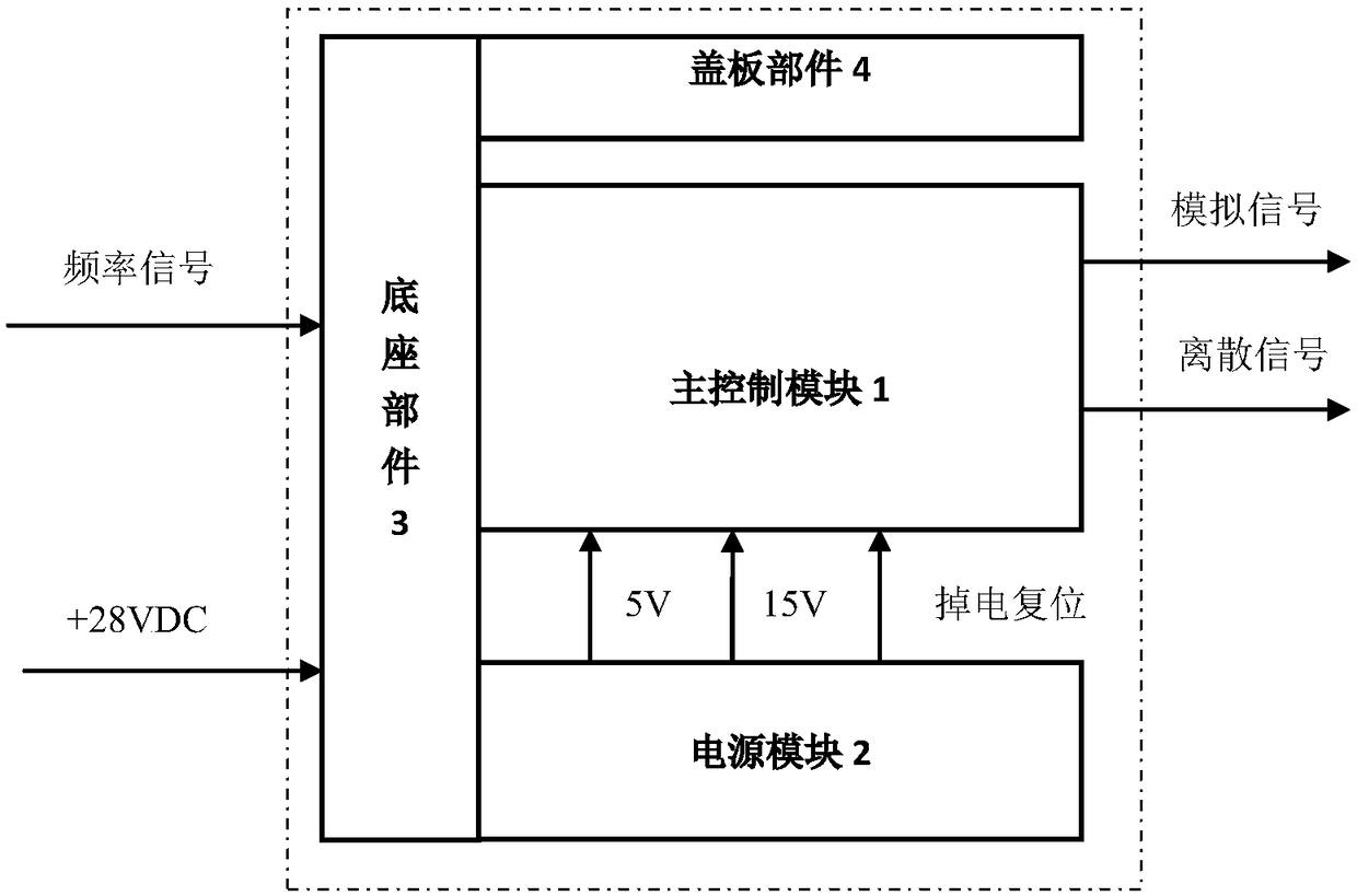
[0027] Such as figure 1 As shown, the rotor speed monitoring processor is composed of a main control module 1 , a power module 2 , a base part 3 and a cover part 4 .

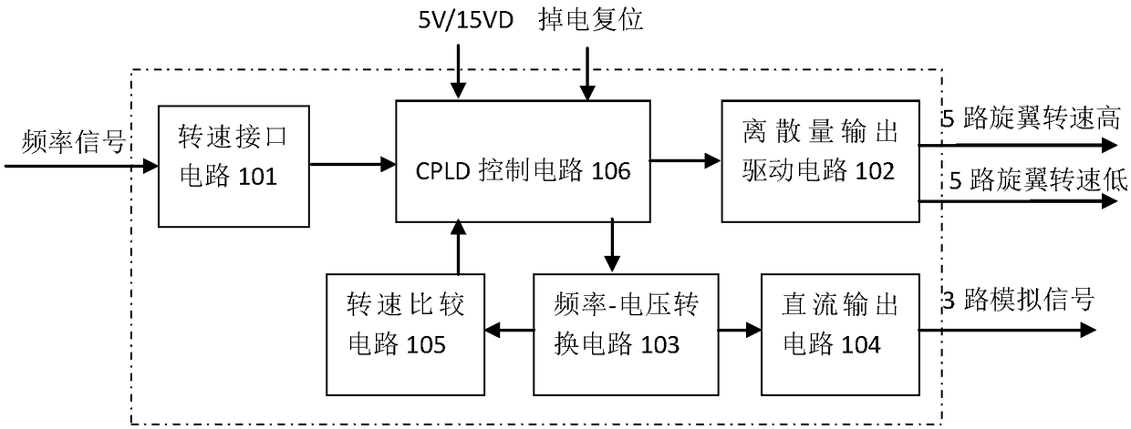
[0028] Such as figure 2 As shown, the main control module 1 includes a rotational speed interface circuit 101 , a discrete output drive circuit 102 , a frequency-voltage conversion circuit 103 , a DC output circuit 104 , a rotational speed comparison circuit 105 and a CPLD control circuit 106 . Wherein, the CPLD control circuit 106 is respectively connected with the rotational speed interface circuit 101, the discrete output drive circuit 102, the frequency-voltage conversion circuit 103 and the rotational speed comparison circuit 105; the rotational speed interface circuit converts the frequency signal into a square wave and outputs it to the CPLD control circ...


PUM


Abstract

The invention relates to a rotor speed monitoring processor, comprising a main control module, a power module, a base component and a cover component. The processor is characterized in that the main control module comprises a speed interface circuit, a discrete output drive circuit, a frequency-voltage conversion circuit, a DC output circuit, a speed comparison circuit, and a CPLD control circuit.The CPLD control circuit is respectively connected with the speed interface circuit, the discrete output drive circuit, the frequency-voltage conversion circuit, and the speed comparison circuit, andthe frequency-voltage conversion circuit is respectively connected with the DC output circuit and the speed comparison circuit. The rotor speed monitoring processor introduces the helicopter rotor speed magnetic sensor signal and the onboard power supply to the main control module and the power supply module respectively through the base component. The main control module collects the frequency signal of the speed magnetic sensor, and real-time converts all the collected frequency signals into analog signals and discrete signals for collection by on-board back-end equipment.

Description

technical field [0001] The invention relates to a rotor speed monitoring processor, in particular to a rotor speed monitoring processor which collects and judges frequency signals of a magnetic speed sensor in real time and outputs multiple discrete signals and analog signals. Background technique [0002] In the status monitoring of the rotor speed of the helicopter, the signal of the magnetic speed sensor is generally connected to the corresponding acquisition device for collection, and there is no special equipment for collecting the signal of the magnetic speed sensor. Due to the large number of equipment on the machine to collect the speed signal, the distribution is wide, and the collection and processing methods are different, the parameter values ​​​​of the same signal after collection are inconsistent, and even there are large errors; Abnormal condition of load impedance mismatch. Contents of the invention [0003] Purpose of the invention: [0004] Provide a ro...

Claims


Application Information

Patent Timeline
IPC IPC(8): G01P3/44
CPCG01P3/44
Inventor 陈华田军徐黎
Owner SHAANXI QIANSHAN AVIONICS
Why Eureka
Try Eureka