Method, device and equipment for suppressing range ambiguity based on nonlinear orthogonal waveform

A technology of orthogonal waveform and range blur, applied in the field of synthetic aperture radar imaging, which can solve the problems of high PRF, azimuth ambiguity, and large azimuth bandwidth.

Active Publication Date: 2020-10-02
INST OF ELECTRONICS CHINESE ACAD OF SCI
View PDF8 Cites 0 Cited by
  • Summary
  • Abstract
  • Description
  • Claims
  • Application Information

AI Technical Summary

Problems solved by technology

[0005] In general spaceborne SAR applications, the azimuth bandwidth is large and the PRF is high. In order to ensure the width of the surveying swath, the oversampling rate is low, generally 1.2, so the range ambiguity and azimuth ambiguity exist at the same time, which has a serious impact

Method used


Image

  • Method, device and equipment for suppressing range ambiguity based on nonlinear orthogonal waveform
  • Method, device and equipment for suppressing range ambiguity based on nonlinear orthogonal waveform
  • Method, device and equipment for suppressing range ambiguity based on nonlinear orthogonal waveform

Examples


Embodiment 1

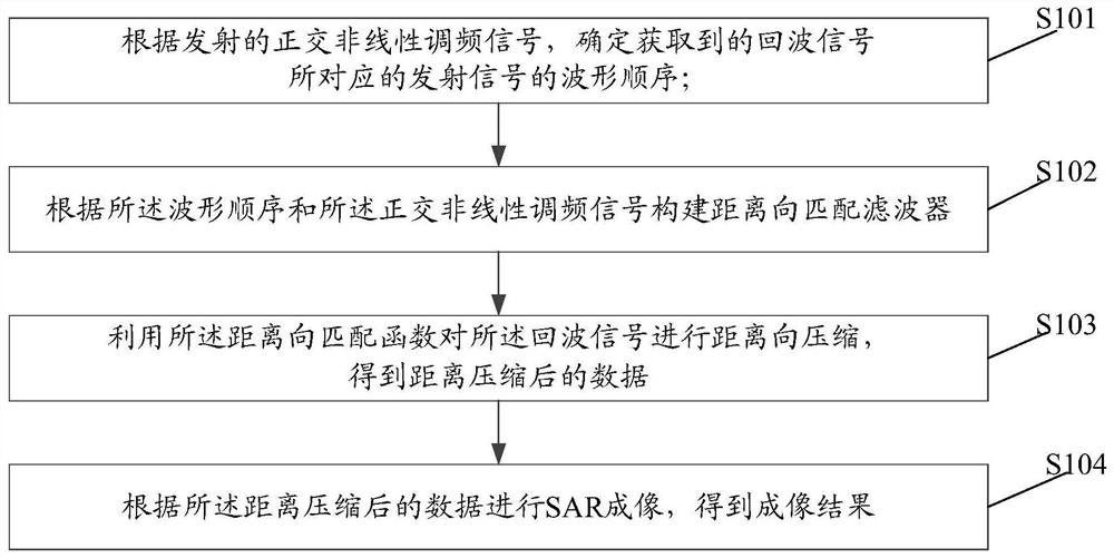
[0038] An embodiment of the present invention provides a range ambiguity suppression method based on a nonlinear orthogonal waveform, figure 1 It is a schematic diagram of the implementation flow of the distance ambiguity suppression method based on the nonlinear orthogonal waveform in the embodiment of the present invention, as shown in figure 1 As shown, the method includes the following steps:

[0039] Step S101, according to the transmitted quadrature non-linear frequency modulation signal, determine the waveform sequence of the transmitted signal corresponding to the acquired echo signal.

[0040] Here, the step S101 may be implemented by a range ambiguity suppression device based on a nonlinear orthogonal waveform, wherein the range ambiguity suppression device based on a nonlinear orthogonal waveform may also be called a SAR imaging device. Further, the SAR imaging device may be an intelligent terminal with computing capability, such as a desktop computer.

[0041] In...

Embodiment 2

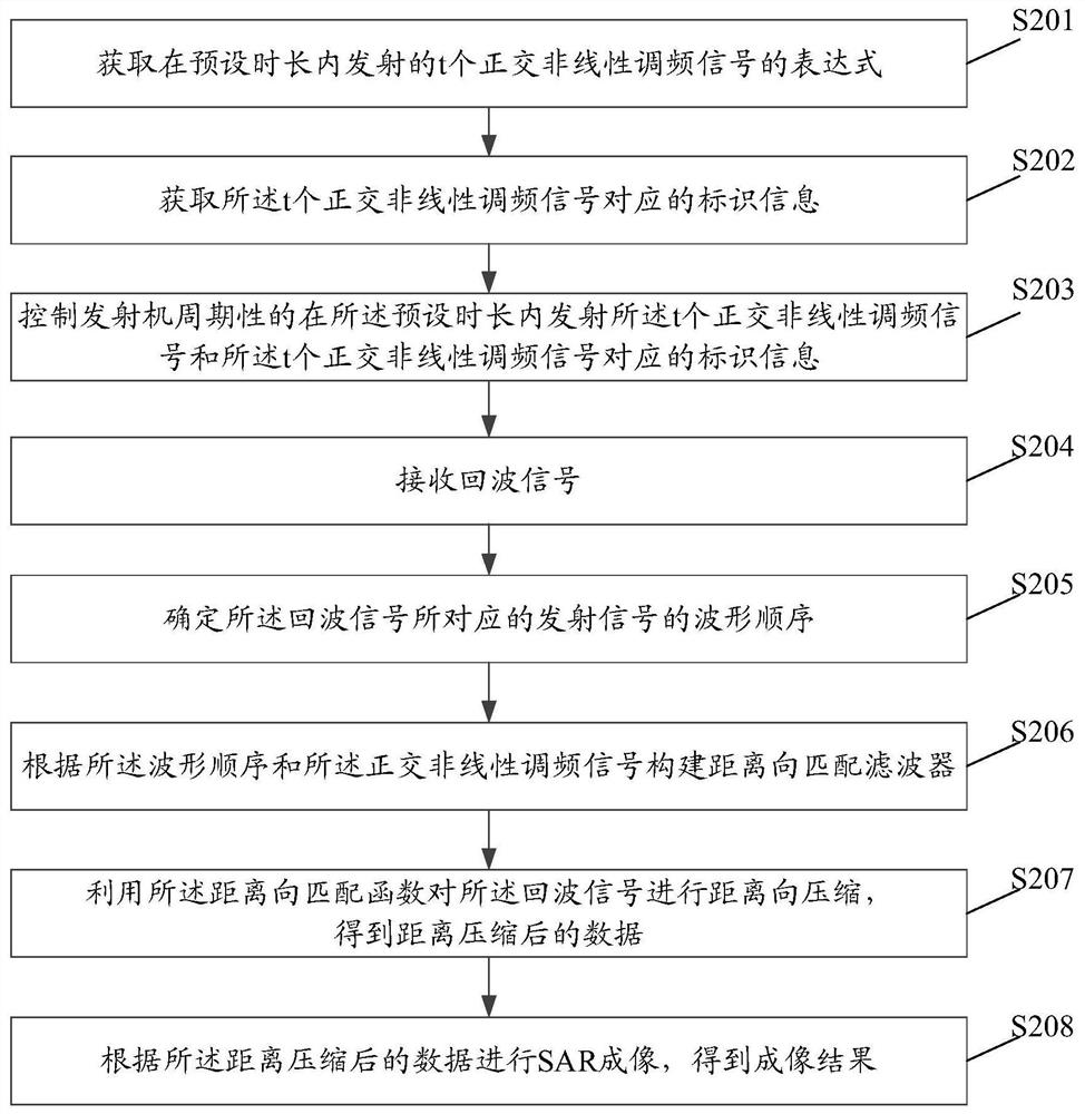
[0056] Based on the foregoing embodiments, embodiments of the present invention provide a range ambiguity suppression method based on a nonlinear orthogonal waveform, which is applied to a range ambiguity suppression device based on a nonlinear orthogonal waveform, that is, a SAR imaging device, figure 2 It is a schematic diagram of the implementation flow of the distance ambiguity suppression method based on the nonlinear orthogonal waveform in the embodiment of the present invention, as shown in figure 2 As shown, the method includes the following steps:

[0057] In step S201, the SAR imaging device acquires t orthogonal non-linear frequency modulation signals transmitted within a preset time period.

[0058] Here, the preset duration is t times the pulse repetition interval, and t is a natural number greater than 1. The quadrature non-linear frequency modulation signal may be artificially set in advance.

[0059] In this embodiment, obtaining t orthogonal non-linear fre...

Embodiment 3

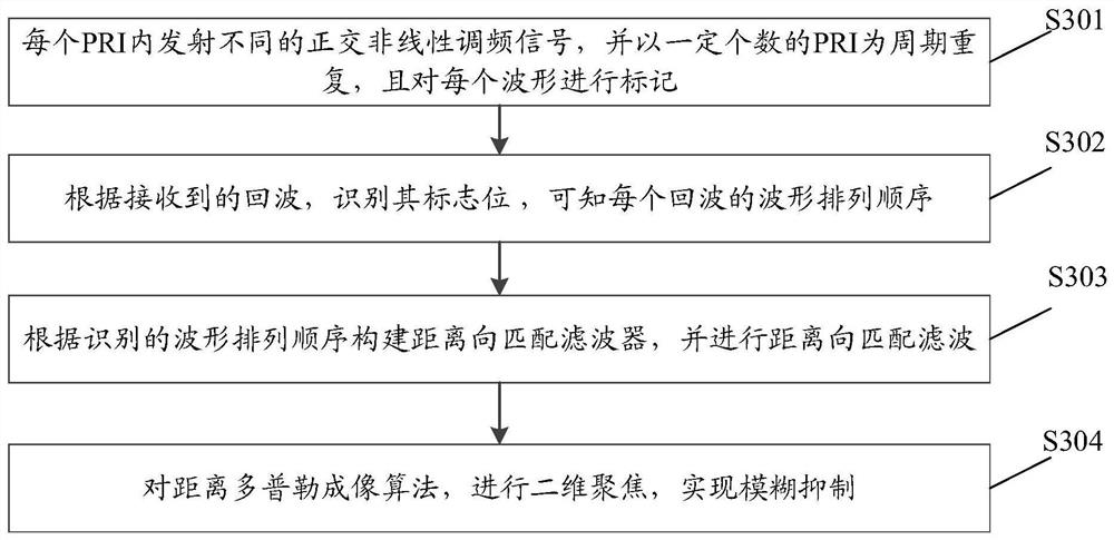
[0088] Based on the foregoing embodiments, embodiments of the present invention further provide a range ambiguity suppression method based on nonlinear orthogonal waveforms, which can suppress range ambiguity by using orthogonal nonlinear frequency modulation signals during SAR imaging. image 3 It is a schematic diagram of the implementation process of SAR imaging in the embodiment of the present invention, such as image 3 As shown, the method includes the following steps:

[0089] Step S301 , when the transmitter transmits a signal, transmit different orthogonal non-linear frequency modulation signals in different PRIs, repeat with a certain number of PRIs as a cycle, and mark each waveform.

[0090] here, as Figure 4 As shown, taking two signals as an example, the signal s is transmitted in the first PRI 1 (t), transmit signal s in the second PRI 2 (t), transmit signal s in the third PRI 1 (t), transmit signal s in the fourth PRI 2 (t), so that the signal is transmit...


PUM


Abstract

The embodiment of the present invention discloses a range ambiguity suppression method, device and equipment based on nonlinear orthogonal waveforms, wherein the method includes: determining the echo signal corresponding to the acquired echo signal according to the transmitted orthogonal nonlinear frequency modulation signal. The waveform sequence of the transmitted signal; according to the waveform sequence and the orthogonal non-linear frequency modulation signal to construct a range-to-matched filter; use the range-to-matching function to perform range-to-compression on the echo signal, and obtain the range-compressed data; performing SAR imaging according to the compressed distance data to obtain an imaging result.

Description

technical field [0001] The present invention relates to synthetic aperture radar (Synthetic Aperture Radar, SAR) imaging technology, and relates to but not limited to a range ambiguity suppression method, device and equipment based on nonlinear orthogonal waveforms. Background technique [0002] Synthetic aperture radar is capable of all-day, all-weather, and global earth observation, and has a wide range of applications. But it is limited by two fundamental problems: [0003] First, the constraints of resolution and mapping bandwidth: the higher the azimuth resolution, the higher the Pulse Repetition Frequency (PRF), and the narrower the available mapping band. Therefore, the azimuth resolution and range swath width cannot be improved at the same time. [0004] Second, the constraint relationship between azimuth ambiguity and range ambiguity: the higher the PRF, the larger the oversampling in the azimuth direction, and the smaller the azimuth ambiguity, the corresponding ...

Claims


Application Information

Patent Timeline
Patent Type & Authority Patents(China)
IPC IPC(8): G01S7/36
CPCG01S7/36G01S13/34G01S13/9004G01S7/282G01S7/292G01S7/41G01S13/9011
Inventor 金国栋王宇邓云凯王伟张永伟刘开雨
Owner INST OF ELECTRONICS CHINESE ACAD OF SCI
Why Eureka
Try Eureka