Protection-type gauze mask

A mask and surface layer technology, applied in the field of masks, can solve the problems of sacrificing comfort, reducing the wearer's wearing comfort, and the inability of gas to be quickly and effectively discharged from the mask, so as to increase the action time and contact area, and enhance the ability of odor adsorption and filtration. , better customer experience

Inactive Publication Date: 2019-02-19
名典上品(北京)信息技术有限公司
View PDF16 Cites 7 Cited by
  • Summary
  • Abstract
  • Description
  • Claims
  • Application Information

AI Technical Summary

Problems solved by technology

[0005] There is the following defect in the above-mentioned prior art scheme: its diaphragm has only a complete circular sheet, so when the wearer is exhaling, the gas can only be scattered outwards through the surroundings of the diaphragm, which will make the wearer When exhaling, the air flow is relatively concentrated, and the resistance of the gas to diffuse from the mask to the outside is relatively large. The exhaled gas cannot be quickly and effectively discharged from the mask, so that moisture is generated inside the mask, and the wearer will feel oppressed, thereby reducing the wearer's wearing comfort
[0007] Its disadvantages are: but the key problem in the limited production process of electret melt-blown filter materials used in mask products in the industry, that is, with the ejection and superposition of melt-blown fibers, the inter-fiber structure that should theoretically be in a fluffy state will occur. Collapse, the space between fibers is reduced, so that the dust holding capacity does not increase but decreases, which makes it difficult to achieve low breathing resistance and high dust holding capacity by increasing the thickness (gram weight) of the electret meltblown filter material
However, the performance of good-quality needle-punched electrostatic cotton is often only 60-75% of the electret melt-blown filter material of the same gram weight. If you want to achieve higher dust holding and filtering effects, the overall thickness of the mask will increase significantly, which will sacrifice Comfort increases breathing resistance, which increases the cost and affects the appearance and texture of mask products

Method used


Image

  • Protection-type gauze mask
  • Protection-type gauze mask
  • Protection-type gauze mask

Examples


Embodiment 1

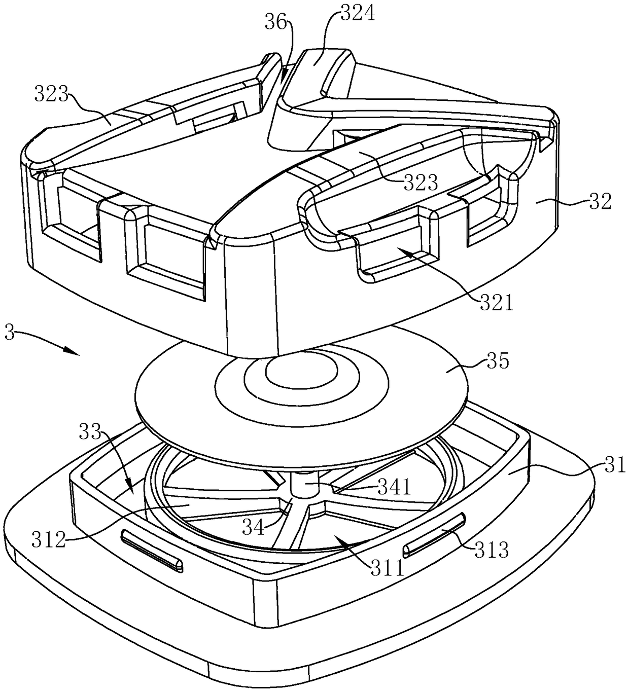
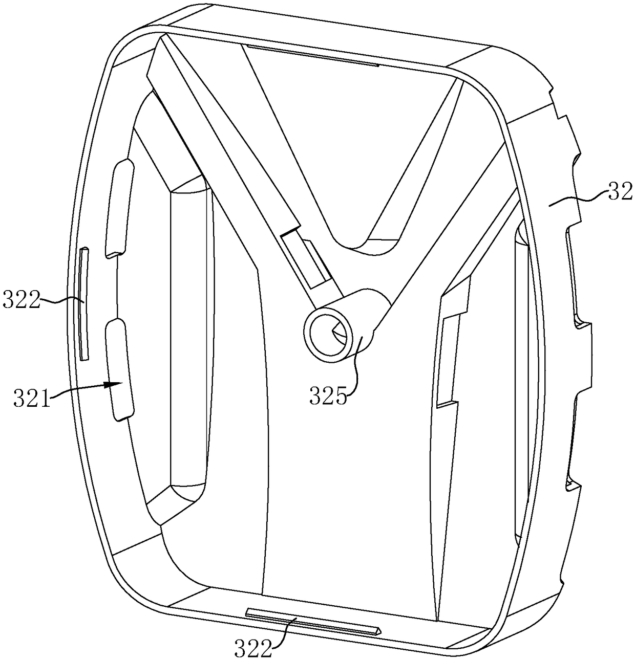
[0080] combine Figure 6 , on the side of the valve cover 32 away from the base 31 is fixedly connected with a first rib 323, two first ribs 323 are provided, and the two first ribs 323 are located on both sides of the valve cover 32 away from each other and parallel to each other , the air outlet holes 321 are provided on both sides of the first rib 323 .

[0081] One end of the first rib 323 is fixedly connected with a second rib 324, the second rib 324 is "V" shaped, and is located between the two first ribs 323, the first rib 323 and the second rib 324 Forming an "M" shape, the air outlet hole 321 is also opened on the outer sidewall of the second rib 324 , and a flow channel 36 is formed between the first rib 323 and the second rib 324 .

[0082] When the wearer exhales, the generated gas is discharged from the air outlet holes 321. Since the air outlet holes 321 are opened on both sides and the middle position of the valve cover 32, the gas can be shunted, which can sho...

Embodiment 2

[0084] combine Figure 6 and Figure 7 As shown, several air outlet holes 321 are opened on the valve cover 32, and the air outlet holes 321 communicate with the cavity 33 and the outside air. A plurality of valve holes 352 are provided on the filter valve sheet 35, and microvalve sheets 353 are arranged one by one at the valve holes 352, and several through holes 311 are provided on the base 31, and the cavity 33 communicates with the outside through the through holes 311. In communication with each other, a mounting seat 314 for supporting the microvalve sheet 353 is provided at the through hole 311 , and the mounting seat 314 and the microvalve sheet 353 are arranged in one-to-one correspondence. The filter valve sheet 35 and the micro-valve sheet 353 are of non-woven fiber structure, preferably using KN95 grade filter material performance material structure.

[0085] The shape of the microvalve sheet 353 can be a single figure or a combined figure of various regular or i...

Embodiment 3

[0092] Such as Figure 9 As shown, a through hole 311 is opened on the base 31, the cavity 33 communicates with the outside through the through hole 311, and several support rods 312 are fixedly connected at the through hole 311, and several support rods 312 are arranged around the circumference of the through hole 311. Distributed in an array, the ends of several support rods 312 away from the inner wall of the through hole 311 of the base 31 are fixedly connected together to form the connecting portion 34 . Wherein, the number of connecting rods can be one or more, and an auxiliary support rod 316 is fixedly arranged between two adjacent support rods 312. One end of the auxiliary support rod 316 is fixed on the inner wall of the through hole 311, and the other end is free. At the end, the number of supporting rods 312 can be effectively reduced by setting the auxiliary rods 316, which is relatively stable when supporting the filter valve plate 35. At the same time, the cross...


PUM


Abstract

The invention relates to a protection-type gauze mask. The protection-type gauze mask comprises a gauze mask body, ear bands and a breather valve arranged on the gauze mask body, and the gauze mask body comprises a face layer, a bottom layer and a filter layer sandwiched between the face layer and the bottom layer. The protection-type gauze mask has the advantages that when a wearer uses the protection-type gauze mask, the breathing resistance is small, breathing is smoother, and the comfort degree of the wearer is improved.

Description

technical field [0001] The invention relates to the technical field of masks, in particular to a protective mask. Background technique [0002] Breathing valve masks are designed for people's health, and are used to filter visible or invisible substances that are harmful to the human body in the air, so as not to have a bad influence on the human body. [0003] In hot and humid working environments with poor ventilation or heavy labor, using a mask with a breathing valve can help the wearer to breathe more comfortably. The working principle of the breathing valve is that the positive pressure of the exhaust gas blows open the filter valve when exhaling, so as to quickly remove the exhaust gas in the body and reduce the stuffy feeling when using the mask, and the negative pressure when inhaling will automatically close the valve to avoid Inhalation of pollutants from the external environment. [0004] The existing authorized notification number that can be referred to is th...

Claims


Application Information

Patent Timeline
Patent Type & Authority Applications(China)
IPC IPC(8): A41D13/11
CPCA41D13/11
Inventor 王岩
Owner 名典上品(北京)信息技术有限公司
Why Eureka
Try Eureka