A step-by-step clamping valve prosthesis and its delivery system

A valve prosthesis and delivery system technology, applied in the field of medical devices, can solve the problems of the fatigue resistance of the clamping body, the impact of the clamping capacity of the clamping body, and the unsatisfactory clamping stability. clamping effect, avoid contact, increase the effect of the clamping surface

Active Publication Date: 2020-10-20
NINGBO JENSCARE BIOTECHNOLOGY CO LTD
View PDF8 Cites 0 Cited by
  • Summary
  • Abstract
  • Description
  • Claims
  • Application Information

AI Technical Summary

Problems solved by technology

There are three problems with this design. One is that the bracket and the clamping body are cut in one piece. The clamping capacity of the clamping body is greatly affected by the wall thickness of the pipe, and the wall thickness also affects the supporting force of the bracket. When the supporting force of the bracket is too large Sometimes it will cause compression of the tissues near the mitral valve, such as the normal work of the aortic valve. It is difficult for the designer to balance the support force of the stent while pursuing a larger clamping force for the clamping body; the second is that the process of flipping and shaping the clamping body is complicated , even if the shape is successful, the fatigue resistance of the clamping body is still open to question; the third is that the clamping body can only cover and clamp from the area of ​​the valve leaflet that is relatively free of chordae, and its clamping stability is not ideal; The same clamping body can only clamp a single leaflet, and regurgitation between the leaflets cannot be avoided

Method used


Image

  • A step-by-step clamping valve prosthesis and its delivery system
  • A step-by-step clamping valve prosthesis and its delivery system
  • A step-by-step clamping valve prosthesis and its delivery system

Examples


specific Embodiment 1

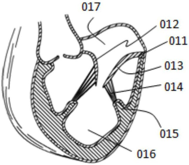
[0055] Such as Figure 1a as shown, Figure 1a The left atrium 017 and the left ventricle 016 of the left half of the heart are shown, and blood can flow into the left ventricle 016 from the left atrium 017 in one direction. At the junction of the left atrium 017 and the left ventricle 016, it is the mitral valve body of the heart, which includes the mitral valve ring 011, the anterior valve 012, the posterior valve 013, the chordae 014, the papillary muscle 015, the anterior valve 012 and the posterior valve The petals 013 are connected to the corresponding papillary muscles 015 through their respective chordae 014 . In a healthy heart organ, when the papillary muscle 015 contracts, it pulls the chordae 014, and the mitral valve body is in a conduction state; when the papillary muscle 015 relaxes, the chordae 014 is relaxed, and the mitral valve body is in a closed state.

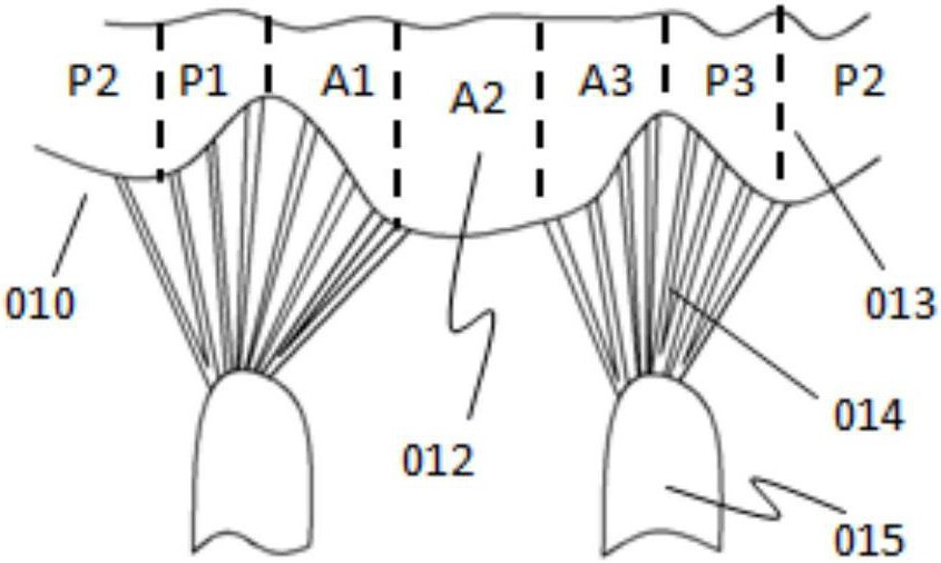
[0056] Such as Figure 1b As shown, those skilled in the art usually divide the mitral valve into se...

specific Embodiment 2

[0080] Such as Figures 11a-11c As shown, as another embodiment, a step-by-step clamping valve prosthesis 200 includes a stent body 210 and two clamping bodies 220, the stent body 210 has a channel 2101 for blood circulation, and the clip The holding body 220 includes a first holding body 221 and a second holding body 222, one end of the first holding body 221 is connected to the support body 210, and the other end of the first holding body 221 is a free end, The second clamping body 222 is connected to the first clamping body 221, and the clamping body 220 has three forms in sequence from compression to complete release, the first form being the first clamping body 221 and the first clamping body 221. The second clamping body 222 is compressed and limited; the second form is that the second clamping body 222 is limited, and the first clamping body 221 can be connected from the anterior valve, the posterior valve, or the anterior valve and the posterior valve of the mitral val...

specific Embodiment 3

[0098] Such as Figures 18a-18d As shown, as another embodiment, a step-by-step clamping valve prosthesis 300 is different from the above-mentioned specific embodiments in that the leaflet body 330 is not pre-fixed on the stent body 310, but is After the stent body 310 is completely released, the leaflet body 330 is released in the stent body 310 again. In order to realize the above-mentioned technical solution, the present invention also provides a delivery system 360 of a step-by-step clamping type valve prosthesis, which includes a step-by-step clamping type valve prosthesis 300, an outer sheath 361, a stent sheath 362, a stent The sheath core 363 and the clamping body sheath 364, the sub-step clamping valve prosthesis 300 includes a stent body 310 and at least one clamping body 320, the stent body 310 has a channel for blood circulation, the clamping The body 320 includes a first clamping body 321 and a second clamping body 322, one end of the first clamping body 321 is c...


PUM


Abstract

The application relates to a step-by-step clamping valve prosthesis and its delivery system. The valve prosthesis includes a stent body and a clamping body. The stent body has a channel for blood circulation, and the clamping body includes a first clamping body and a clamping body. The second clamping body, one end of the first clamping body is connected to the support body, and the other end is a free end, the second clamping body is connected to the first clamping body, and the clamping body has three forms from compression to complete release, The first form is that both the first clamping body and the second clamping body are compressed and restricted; the second form is that the second clamping body is restricted, and the first clamping body extends along the radial direction of the stent body to reach the valve leaflet and between the heart walls; the third shape is that the second clamping body protrudes from the first clamping body, extends along the circumference of the stent body and abuts against the outer surface of the stent body, and the autogenous valve leaflet and adjacent tissues are clamped at the second Between the second clamping body, the first clamping body and the support body, the contact surface between the valve prosthesis and the autologous tissue can be increased, the position stability in the heart can be improved, and the success rate of the operation can be improved.

Description

Technical field: [0001] The invention belongs to the field of medical devices, and in particular relates to a step-by-step clamping valve prosthesis and a delivery system thereof. Background technique: [0002] The mitral valve body consists of the mitral annulus, anterior valve, posterior valve, chordae, papillary muscles, left atrium and left ventricle. The anterior leaflet and the posterior leaflet are jointly divided, which are located in the anterolateral part and the posterior middle part, respectively. The chordae from the bilateral papillary muscles are inserted into the valve leaflets. According to the different insertion sites, the chordae are divided into three types as a whole: commissural tendons, anterior lobe tendons, and posterior lobe tendons. The single tendon from the papillary muscle bifurcates in a fan shape and inserts into the commissure area of ​​the leaflets. The anterior leaflet tendons insert into the free edge of the anterior leaflet to provide ...

Claims


Application Information

Patent Timeline
Patent Type & Authority Patents(China)
IPC IPC(8): A61F2/24
CPCA61F2/24A61F2/2409A61F2/2412A61F2/2436A61F2/2418A61F2220/0008A61F2250/0069A61F2220/0025
Inventor 吕世文李毅斌陈志鲁侃
Owner NINGBO JENSCARE BIOTECHNOLOGY CO LTD
Why Eureka
Try Eureka