Hydraulic rail stretching machine for railway

A stretching machine and hydraulic technology, applied in the field of hydraulic rail stretching machines for railways, can solve the problems of reducing friction, excessive wear, time-consuming and labor-intensive, etc., to ensure the clamping effect, ensure the neutrality, and facilitate the processing work. Effect

Active Publication Date: 2021-11-26
CHANGSHA WEIPING MACHINERY
View PDF0 Cites 0 Cited by
  • Summary
  • Abstract
  • Description
  • Claims
  • Application Information

AI Technical Summary

Problems solved by technology

[0003] But the existing hydraulic rail stretching machine still has the following deficiencies in the actual operation process: first, the traditional hydraulic rail stretcher mainly relies on the friction between the inclined iron and the rail to clamp the rail, and the stretching action During the process, use the cooperation of the clamp and the inclined iron to slowly clamp and clamp the rail, so that the sliding friction between the inclined iron and the rail gradually becomes static friction, and the inclined iron is a vulnerable part, and the inclined iron faces the rail. The surface is easy to cause excessive wear during the stretching process, which will greatly reduce the friction force, and the situation that the friction resistance is less than the pulling force of the hydraulic cylinder will cause the inclined iron to move together with the inclined iron seat, that is, slipping will occur, and the rail cannot be clamped to achieve pulling Therefore, it is necessary to replace the inclined iron frequently; secondly, when the traditional rail tensioner is stretching the rail, it is difficult to ensure that the two sections of the rail have good alignment, that is, after the stretching is completed, the joints of the two ends of the rail Misalignment is prone to occur, resulting in the inability to carry out subsequent processing and repair work on the rail, and it needs to be re-aligned for stretching, which is time-consuming and laborious

Method used


Image

  • Hydraulic rail stretching machine for railway
  • Hydraulic rail stretching machine for railway
  • Hydraulic rail stretching machine for railway

Examples


Embodiment Construction

[0023] The technical solutions in the embodiments of the present invention will be clearly and completely described below with reference to the accompanying drawings in the embodiments of the present invention. Obviously, the described embodiments are only a part of the embodiments of the present invention, but not all of the embodiments. Based on the embodiments of the present invention, all other embodiments obtained by those of ordinary skill in the art without creative efforts shall fall within the protection scope of the present invention.

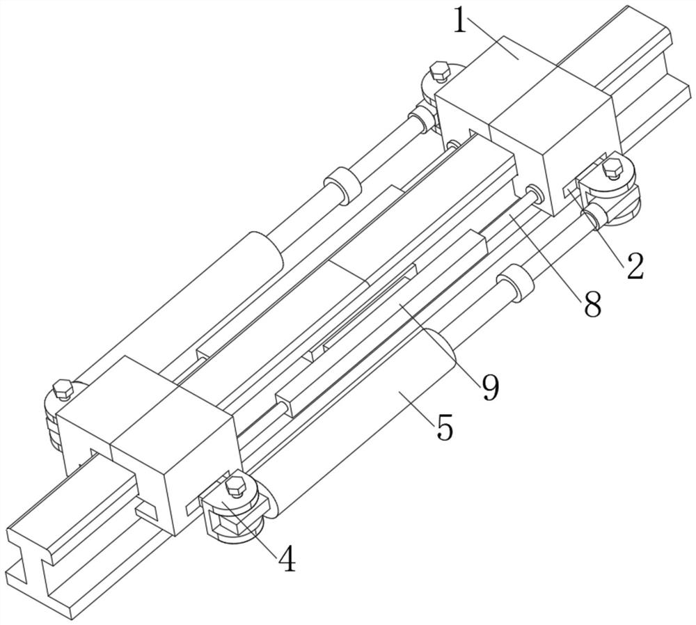
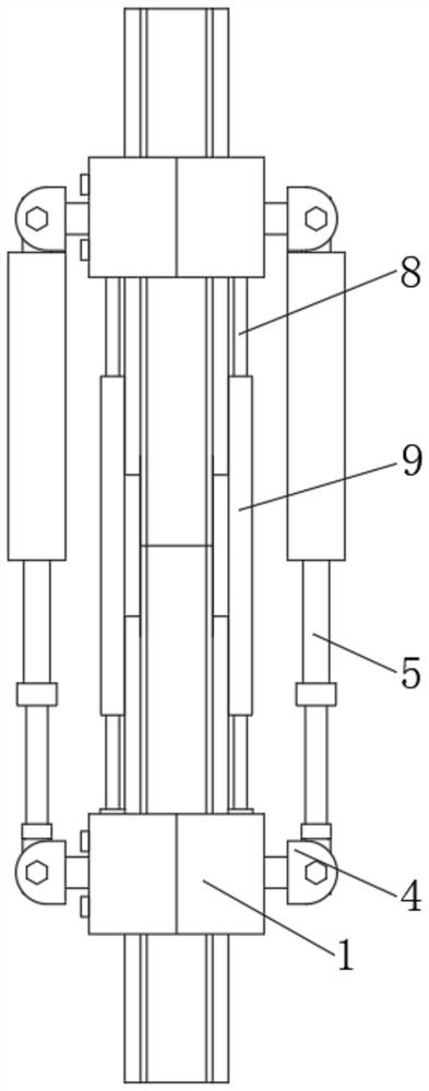
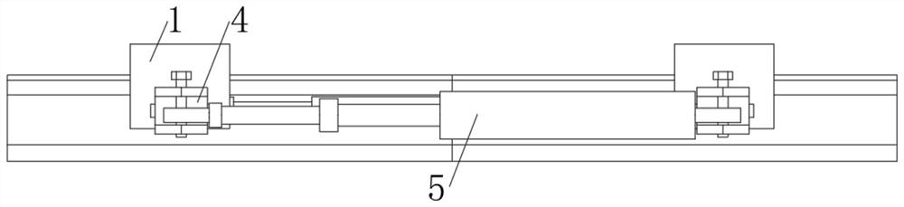
[0024] see Figure 1-8 , a railway hydraulic rail stretching machine, including two rail clamps 1, the left and right sides of the rail clamp 1 are provided with through holes 2, the inner movable sleeve of the rail clamp 1 is connected with a rotating shaft 3, and the rotating shaft The middle part of 3 is fixedly connected with a rotating member 4, one end of the rotating member 4 is movably sleeved with a hydraulic cylinder 5, and ...


PUM


Abstract

The invention relates to the technical field of rail transit equipment, and discloses a railway hydraulic rail stretching machine, which includes two rail clamps, and through holes are opened on the left and right sides of the rail clamps. A rotating shaft is movably socketed inside, and a rotating part is fixedly connected to the middle part of the rotating shaft. One end of the rotating part is movably connected to a hydraulic cylinder, and the other end of the rotating part is fixedly connected to a clamping block. Supporting push rods that are movably socketed with the rail clamp are arranged above and below one side of the holding block. Through the setting of the correction device, when the rail clamp clamps the rail and stretches it, it will drive the two symmetrical support rods on both sides to move inward synchronously, and squeeze the trapezoidal block through the slope of the pressing rod, forcing the trapezoidal block to One side of the rail slides, and the spring and the top plate are squeezed, and the two sections of the rail that are about to be connected are corrected by the extrusion of the top plates on both sides to ensure the neutrality of the two sections of the rail, which is convenient for the subsequent processing of the rail.

Description

technical field [0001] The invention relates to the technical field of rail transit equipment, in particular to a hydraulic rail stretching machine for railways. Background technique [0002] The hydraulic rail tensioner is mainly used in the seamless stress relief of rails and the laying of long rails on railways. In the stress relief operation of seamless lines, after releasing the rail fasteners, when the rail temperature reaches the standard requirements, the stress of the rail can be freed In the released state, apply a pre-calculated pulling force to ensure the gap between the rails. Use the hydraulic pump station to adjust the length of the stretching cylinder, then press the other end of the clamp inclined iron tightly, directly drive the hydraulic cylinder station, the piston moves, with the increase of the pulling force, the rail is clamped tighter by the inclined iron, thereby holding the rail. It moves in the opposite direction of the tension, thereby realizing ...

Claims


Application Information

Patent Timeline
Patent Type & Authority Patents(China)
IPC IPC(8): E01B29/46
CPCE01B29/46
Inventor 谢忠雷
Owner CHANGSHA WEIPING MACHINERY
Why Eureka
Try Eureka