
Powerful pliers for pipe butt-joint clamping

A technology of forceps and pipes, applied in the field of pipe butt clamping forceps, which can solve the problems of welding misalignment of two pipe heads, small clamping jaw width, inconvenient welding, etc., to achieve rapid adjustment, enlarge clamping size, reduce The effect of adjusting the difficulty

Inactive Publication Date: 2019-02-19
李昊一
View PDF12 Cites 4 Cited by
  • Summary
  • Abstract
  • Description
  • Claims
  • Application Information

AI Technical Summary

Problems solved by technology

[0003] When welding two round pipes with the same diameter, in order to ensure the welding quality, it is necessary to accurately align the two pipes. This is a key task. For the butt joint of pipes with a diameter less than 30mm, a universal clamping tool is often used ( Such as water pump pliers, pipe wrench, round pliers, etc.), although this is a more convenient and quick method, but because the width of the clamping jaws of these tools is small, it is difficult to clamp them reliably, and it is not convenient for welding. The butt joint of two individual pipes with larger diameters is often placed in a V-shaped tool. When the length of the two pipes exceeds the length of the V-shaped tool, the coaxiality of the two pipes must be carefully adjusted. , in maintenance and installation, it is quite time-consuming and labor-intensive work to connect two suspended pipes. Therefore, in the existing pipe butt joint, not only the efficiency is low, but also the welding misalignment of the two pipe heads due to improper alignment is also a problem. recurring things

Method used


Image

  • Powerful pliers for pipe butt-joint clamping
  • Powerful pliers for pipe butt-joint clamping
  • Powerful pliers for pipe butt-joint clamping

Examples


Embodiment Construction

[0022] The technical solutions of the embodiments of the present invention will be clearly and completely described below in conjunction with the accompanying drawings of the present invention.

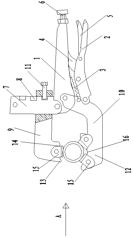
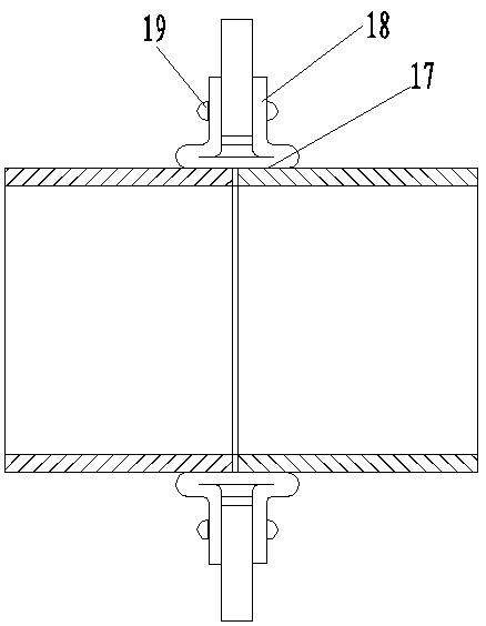
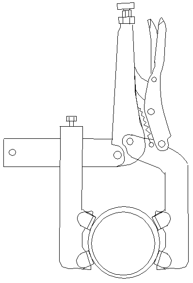
[0023] Such as Figure 1~2 As shown, a pipe butt clamping forceps disclosed by the present invention is mainly aimed at the butt joint and welding between small pipes with a pipe diameter of 25-64 mm. The specific structure includes a pliers head and a pliers body. The structure of the pliers body It includes a large pliers handle 1, a small pliers handle 2, a tension spring 3, a support rod 4, a disengagement handle 5 and an adjusting screw 6. The support bar 4 is hinged at the middle of the small pliers handle and supported between the small pliers handle 2 and the large pliers Between the handles 1, the disengagement handle 5 is hinged at the rear part of the handle 2 of the small pliers, and the adjusting screw 6 is installed at the tail part of the handle 1 of the large pliers. ...


PUM


Abstract

The invention discloses a pair of powerful pliers for pipe butt-joint clamping. The powerful pliers comprise a pliers head and a pliers body, wherein the pliers body comprises a large pliers handle, asmall pliers handle, a disengage handle, a tension spring, a supporting rod and a regulating screw; the front end of the large pliers handle is riveted and welded with a slide rod, and is perpendicular to the large pliers handle; the pliers head comprises a movable pliers head and a sliding pliers head; the sliding pliers head is arranged the slide rod in a sleeving mode, and is fixed in up-downposition through a fastening screw at the rear end; the movable pliers head is L-shaped, and the rear end of the movable pliers head is hinged with the large pliers handle and the small pliers handle;the front end of the sliding pliers head and the front end of the movable pliers head are each provided with a widened clamping platform; the two ends of the clamping platform are provided with up-warp limiting parts, so that the clamping surfaces are trapezoidal, and one or two clamping claws are hinged in the clamping surfaces; and a butt-joint tube is placed between upper and lower clamping surfaces, so that fixed splicing is realized through clamping of upper and lower clamping claws; and seam-slicing welding is performed in a seam between the upper and lower clamping claws.

Description

technical field [0001] The invention relates to a pliers hand tool, in particular to a pipe butt clamping pliers. Background technique [0002] There are many gas and liquid pipelines in all walks of life. These continuous pipelines need to be connected during construction, and different pipelines have different connection methods. For example, ordinary water pipes are connected with standard threads and special accessories. These accessories are such as internal and external joints, tees, elbows, etc. For the connection of stainless steel or seamless steel pipes with thicker walls, flange connections are usually used, or the two pipe heads are directly welded, where welding is Most common practice. [0003] When welding two round pipes with the same diameter, in order to ensure the welding quality, it is necessary to accurately align the two pipes. This is a key task. For the butt joint of pipes with a diameter less than 30mm, a universal clamping tool is often used ( Suc...

Claims


Application Information

Patent Timeline
IPC IPC(8): B25B7/02B25B7/04
CPCB25B7/02B25B7/04
Inventor 李昊一李明德
Owner 李昊一
Learn More