Check patentability & draft patents in minutes with Patsnap Eureka AI!

Ball valve locking mechanism controlled by medium pressure

A locking mechanism and medium pressure technology, applied to valve details, valve devices, mechanical equipment, etc., can solve problems such as inconvenient use and no locking mechanism for ball valves

Pending Publication Date: 2019-02-19
天津国际机械有限公司
View PDF0 Cites 0 Cited by
  • Summary
  • Abstract
  • Description
  • Claims
  • Application Information

AI Technical Summary

Problems solved by technology

[0003] The existing ball valve itself has no locking mechanism or only has a manual locking mechanism, which is inconvenient to use

Method used


Image

  • Ball valve locking mechanism controlled by medium pressure

Examples


Embodiment Construction

[0015] In order to make the object, technical solution and advantages of the present invention more clear, the present invention will be further described in detail below in conjunction with the examples. It should be understood that the specific embodiments described here are only used to explain the present invention, not to limit the present invention.

[0016] In order to solve the drawbacks of the existing ball valves without locking or inconvenient locking, the present invention provides a ball valve locking mechanism controlled by medium pressure. This mechanism can realize automatic locking through pressure difference and is easy to operate. In order to further illustrate the structure of the present invention, in conjunction with accompanying drawing detailed description is as follows:

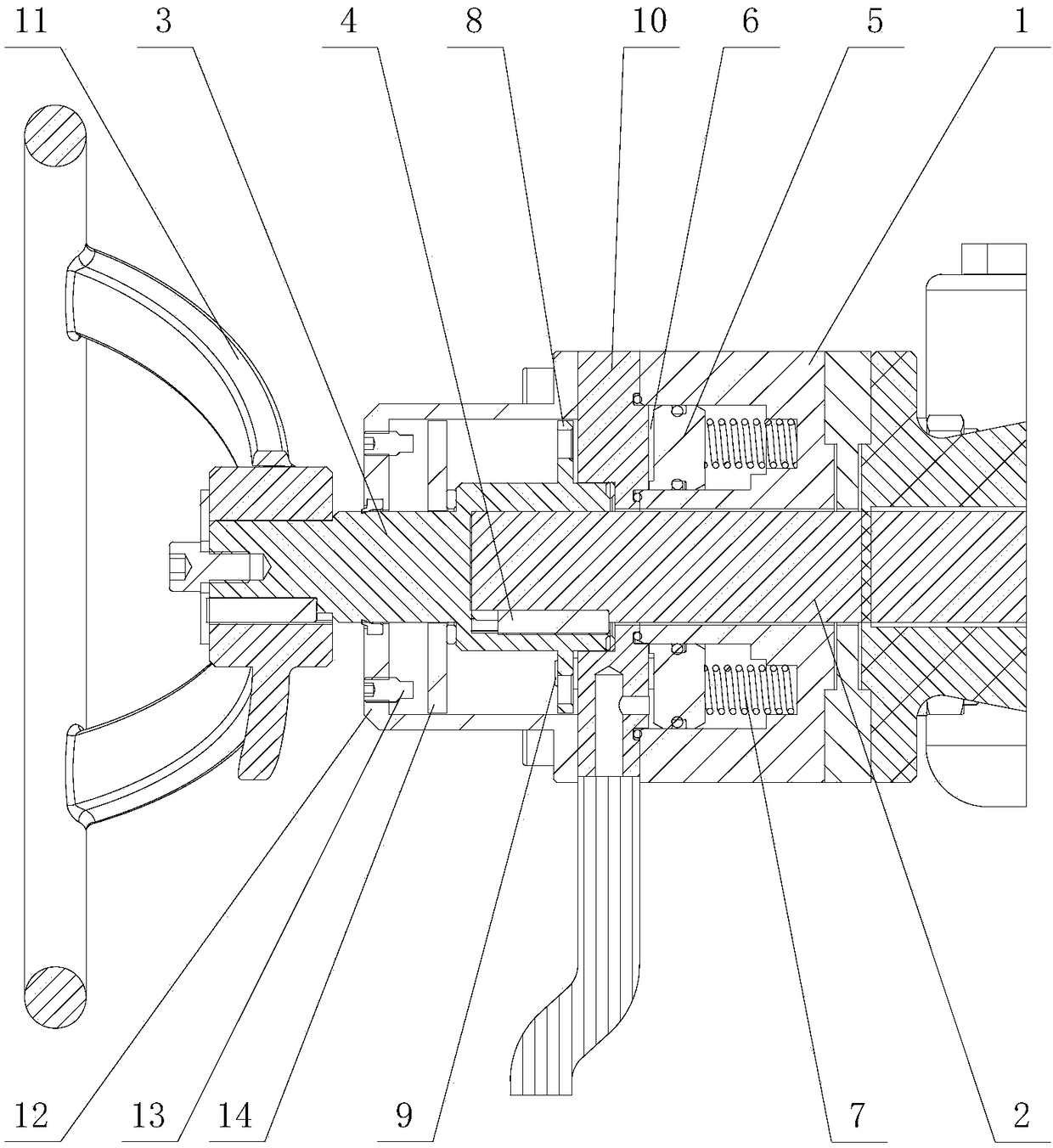
[0017] see figure 1 , a ball valve locking mechanism controlled by medium pressure, has a cylinder 1, and the cylinder 1 is fixed on the valve body of the ball valve. The cylinder b...


PUM


Abstract

The invention discloses a ball valve locking mechanism controlled by medium pressure, and belongs to the technical field of valves. The mechanism comprises a cylinder block; the cylinder block is provided with a middle through hole and an annular piston cavity surrounding the middle through hole; a transmission rod penetrates through the middle through hole; one end of the transmission rod is in transmission connection with a valve rod of a ball valve, and the other end of the transmission rod is connected with a hand wheel rod; a piston ring is assembled in the annular piston cavity of the cylinder block, and divides the annular piston cavity into an elastic pressing cavity far from the hand wheel rod and a punching cavity near the hand wheel rod; a spring is assembled in the elastic pressing cavity; an annular disc plate is arranged at the outer peripheral part of the hand wheel rod; a locking pin is tightly inserted in the cylinder block; one end of the locking pin is fixed on the piston ring, and the other end of the locking pin corresponds to the disc plate; and the disc plate is provided with a locking hole for inserting in the locking pin. An adjusting mechanism is unlockedthrough punching in the punching cavity; and after pressure in the punching cavity disappears, the locking pin plays a role under the effect of the spring to realize automatic locking, so that the operation is convenient.

Description

technical field [0001] The invention belongs to the technical field of valves, in particular to a ball valve locking mechanism controlled by medium pressure. Background technique [0002] The ball valve is a valve in which the ball is driven by the valve stem and rotates around the axis of the ball valve to realize on-off. At present, with the continuous improvement of urban heating demand, the pressure level and heating temperature of industrial heating pipes are constantly changing, so the high temperature resistance, high pressure resistance performance of the sealing material of the heating system and the safety requirements of the valve as a whole is constantly improving. [0003] The existing ball valve itself has no locking mechanism or only has a manual locking mechanism, which is inconvenient to use. Contents of the invention [0004] Aiming at the problems existing in the prior art, the present invention provides a ball valve locking mechanism controlled by med...

Claims


Application Information

Patent Timeline
IPC IPC(8): F16K35/10F16K35/02F16K31/60
CPCF16K31/60F16K35/022F16K35/027F16K35/10
Inventor 匡振东周士倩王庆斌
Owner 天津国际机械有限公司
Features
  • R&D
  • Intellectual Property
  • Life Sciences
  • Materials
  • Tech Scout
  • Unparalleled Data Quality
  • Higher Quality Content
  • 60% Fewer Hallucinations
Learn More