A method and device for distributing load cutting amount

A technology of load shedding and distribution method, applied in the field of load shedding distribution methods and devices, can solve problems such as large distribution errors, system instability, and failure to achieve expected control effects, avoid over-cutting or under-cutting, improve The effect of assigning precision

Active Publication Date: 2019-02-19
NR ELECTRIC CO LTD +1
View PDF4 Cites 2 Cited by
  • Summary
  • Abstract
  • Description
  • Claims
  • Application Information

AI Technical Summary

Problems solved by technology

When emergency control is carried out after a power system failure occurs, it is generally necessary to take measures to cut off the machine at the power transmitting end, and to take load shedding measures at the power receiving end. The load-shedding substations of the subordinate load-shedding sub-stations are allocated in proportion. With the expansion of the stability control system, the number of load-shedding sub-stations is also increasing. Large distribution errors may occur. For example, for a stability control system with 20 load shedding sub-stations, if the minimum measurement unit of the system load is 1MW, the maximum possible over- Shedding 10MW load may also undercut 9MW load. Over-cutting load will increase the social impact of the accident. Too much under-cutting load may fail to achieve the expected control effect and even lead to system instability.

Method used


Image

  • A method and device for distributing load cutting amount
  • A method and device for distributing load cutting amount
  • A method and device for distributing load cutting amount

Examples


Embodiment Construction

[0052]The present invention provides a load shedding distribution method. In order to better understand the technical content of the present invention, specific embodiments are given and described as follows with accompanying drawings.

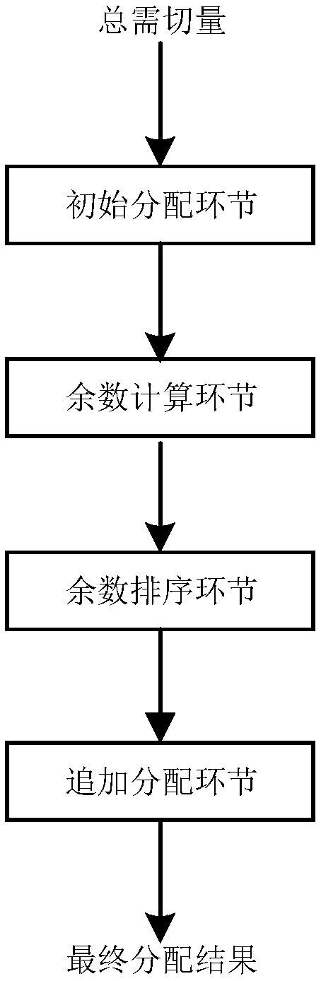
[0053] Such as figure 1 As shown, the solution of the present invention includes the following steps: (1) initial allocation link, (2) remainder calculation link, (3) remainder sorting link, (4) additional allocation link.

[0054] (1) In the initial distribution link, the total demand cut is distributed in proportion to the load shed load of each load shedding substation. Assume that a stability control system has 6 load shedding execution stations, and the total demand cut Pxq=243MW for a certain fault, each The load shedding capacity of the load shedding sub-station is respectively:

[0055] Pkq1=56MW

[0056] Pkq2=67MW

[0057] Pkq3=43MW

[0058] Pkq4=61MW

[0059] Pkq5=80MW

[0060] Pkq6=85MW

[0061] The total shedable load is:

...


PUM


Abstract

A method for distributing load cutting amount includes such steps as (1) proportionally distributing total required cutting amount according to cut load of each load-cutting sub-station, obtaining initial distribution amount of each load-cutting sub-station without rounding during distribution, counting total initial distribution amount of each load-cutting sub-station, calculating difference between total required cutting amount and initial distribution amount to obtain the residual required cutting amount. (2) calculating the distribution remainder of each load shedding sub-station after theinitial distribution module is distributed; (3) allocating residues in descending order; (4) adding and distributing load cutting amount to the remaining required cutting amount at each load sheddingsub-station in the order of the distribution remainder from large to small until the total required cutting amount is equal to the total distribution amount. The invention also discloses a corresponding load-cutting distribution device. The scheme of the invention improves the distribution precision of the load-cutting amount, and can effectively avoid over-cutting or under-cutting caused by rounding.

Description

technical field [0001] The invention belongs to the field of electric power system automation, and in particular relates to a load shedding distribution method and device in the electric power system. Background technique [0002] With the increasing expansion of the power system, regional power grid interconnection and west-east power transmission, large-capacity, long-distance, ultra-high voltage and ultra-high voltage transmission, AC-DC parallel transmission, centralized access to a large number of new energy sources, and the upcoming operation of the power market, etc. , so that the stability of the power system is more prominent than before. The power system stability control technology and stability control system have been widely used in various power grids across the country, and have become an indispensable part of the daily operation of the power grid. When emergency control is carried out after a power system failure occurs, it is generally necessary to take meas...

Claims


Application Information

Patent Timeline
Patent Type & Authority Applications(China)
IPC IPC(8): G06Q10/06G06Q50/06
CPCG06Q10/06312G06Q50/06Y02B70/3225Y04S20/222
Inventor 白杨任祖怡夏尚学王鹏翔王良徐柯李龙龙祝万高楠王君超
Owner NR ELECTRIC CO LTD
Why Eureka
Try Eureka