Image processing method and apparatus, electronic device and computer-readable medium
An image processing and processor technology, applied in the field of image processing, can solve problems such as inability to run in real time and grid computing time-consuming, and achieve the effect of alleviating low processing efficiency and improving performance
- Summary
- Abstract
- Description
- Claims
- Application Information
AI Technical Summary
Problems solved by technology
Method used
Image

Examples
Embodiment 1
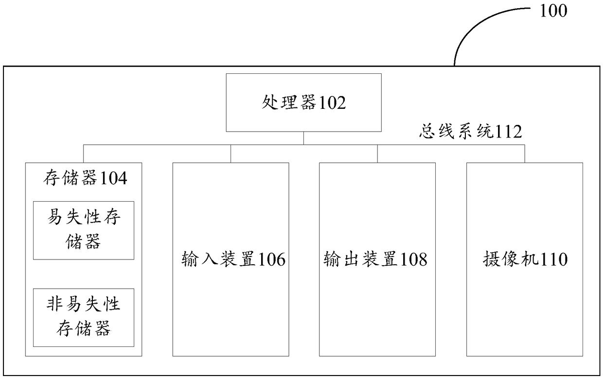
[0034] First, refer to figure 1 The electronic device 100 for implementing the embodiments of the present invention will be described, and the electronic device can be used to run the image processing methods of the various embodiments of the present invention.
[0035] Such as figure 1As shown, the electronic device 100 includes one or more processors 102, one or more memories 104, an input device 106, an output device 108, and a camera 110. These components are connected via a bus system 112 and / or other forms of connection mechanisms (not shown). out) interconnection. It should be noted that figure 1 The components and structure of the electronic device 100 shown are only exemplary, not limiting, and the electronic device may also have other components and structures as required.
[0036] The processor 102 can be a digital signal processor (DSP, Digital Signal Processing), a field programmable gate array (FPGA, Field-Programmable Gate Array), a programmable logic array (...
Embodiment 2
[0043] According to an embodiment of the present invention, an embodiment of an image processing method is provided. It should be noted that the steps shown in the flowcharts of the accompanying drawings can be executed in a computer system such as a set of computer-executable instructions, and, although A logical order is shown in the flowcharts, but in some cases the steps shown or described may be performed in an order different from that shown or described herein.
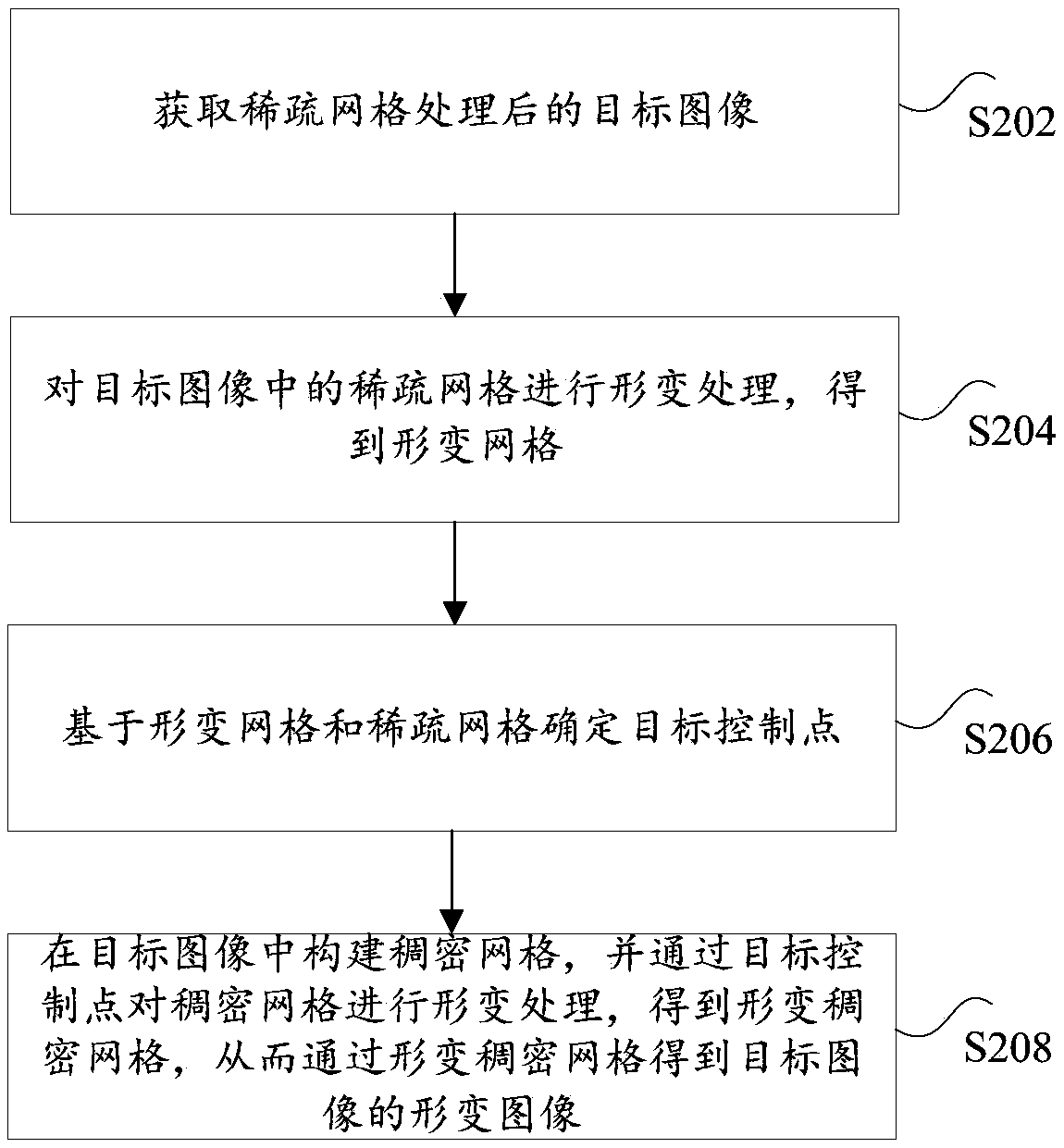
[0044] figure 2 is a flowchart of an image processing method according to an embodiment of the present invention, such as figure 2 As shown, the method includes the following steps:
[0045] Step S202, acquiring the target image processed by the sparse grid;
[0046] Step S204, deforming the sparse grid in the target image to obtain a deformed grid;
[0047] Step S206, determine target control points based on the deformed grid and the sparse grid, wherein the target control points include original key poin...
Embodiment 3
[0102] The embodiment of the present invention also provides an image processing device, the image processing device is mainly used to execute the image processing method provided in the above content of the embodiment of the present invention, and the image processing device provided in the embodiment of the present invention will be described in detail below.
[0103] Figure 9 is a schematic diagram of an image processing device according to an embodiment of the present invention, such as Figure 9 As shown, the image processing device mainly includes an acquisition unit 10, a first deformation unit 20, a determination unit 30 and a second deformation unit 40, wherein:
[0104] An acquisition unit 10, configured to acquire the target image processed by the sparse grid;
[0105] The first deformation unit 20 is configured to deform the sparse grid in the target image to obtain a deformed grid;
[0106] A determining unit 30, configured to determine a target control point b...
PUM
 Abstract
Description
Claims
Application Information
 - R&D Engineer
- R&D Manager
- IP Professional
- Industry Leading Data Capabilities
- Powerful AI technology
- Patent DNA Extraction
Browse by: Latest US Patents, China's latest patents, Technical Efficacy Thesaurus, Application Domain, Technology Topic.
© 2024 PatSnap. All rights reserved.Legal|Privacy policy|Modern Slavery Act Transparency Statement|Sitemap