

Display substrate, preparation method of display substrate, display device, preparation method of display device and display unit
A technology for display substrates and display devices, applied in the fields of display devices, display devices and their preparations, display substrates and their preparations, can solve the problems of circuit connection area breakage, narrow structure size, damage, etc., and achieves easy removal and stress reduction. , the effect of easy bending process
- Summary
- Abstract
- Description
- Claims
- Application Information
AI Technical Summary
Problems solved by technology
Method used
Image

Examples
Embodiment approach 2
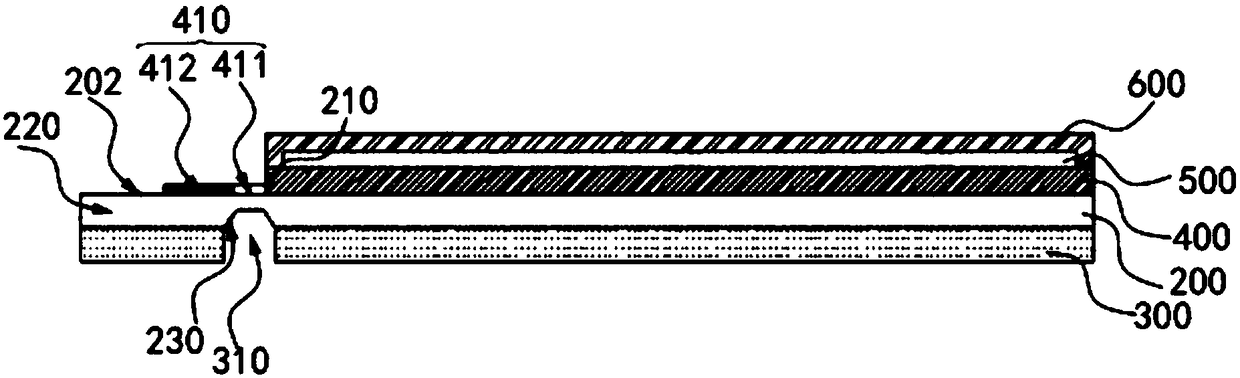
[0102] refer to figure 2 , figure 2A layered view of another embodiment of a display substrate embodying principles of the present disclosure is representatively shown in . In this exemplary embodiment, the design of the display substrate proposed in the present disclosure is substantially the same as that of the above-mentioned first embodiment, and the main design differences will be described below.
[0103] Such as figure 2 As shown, in this embodiment, the cross section of the groove 230 opened on the lower surface of the flexible substrate 200 is roughly trapezoidal. Specifically, the upper bottom of the trapezoid corresponding to the section of the groove 230 (i.e. the shorter one of the two bases of the trapezoid) corresponds to the bottom of the groove 230, and the lower bottom of the trapezoid (i.e. the two bases of the trapezoid) The longer one) corresponds to the notch of the groove 230, and the two sides of the trapezoid correspond to the groove walls on bot...
Embodiment approach 3
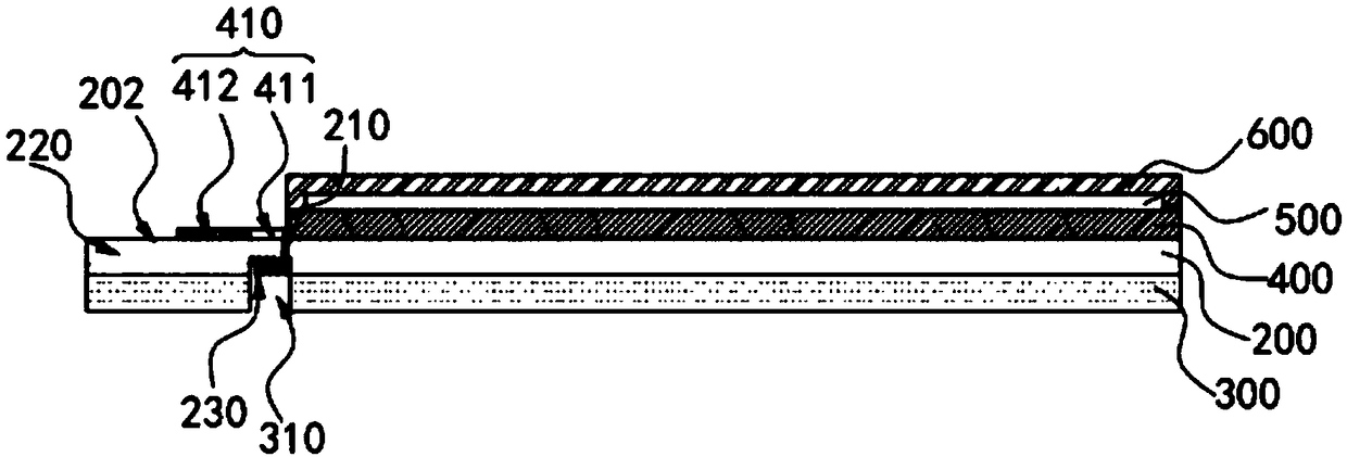
[0107] refer to image 3 , image 3 A layered view of yet another embodiment of a display substrate capable of embodying principles of the present disclosure is representatively shown in . In this exemplary embodiment, the design of the display substrate proposed in the present disclosure is substantially the same as that of the above two embodiments, and the main design differences will be described below.
[0108] Such as image 3 As shown, in this embodiment, the cross-section of the grooves 230 opened on the lower surface of the flexible substrate 200 is substantially grid-shaped. Specifically, the groove 230 is jointly formed by a plurality of sub-grooves 230 arranged in parallel and spaced apart.
[0109] Further, as image 3 As mentioned above, in this embodiment, the cross-section of the sub-grooves 230 is roughly rectangular. Accordingly, after the grooves 230 are bent, the plurality of sub-grooves 230 form a zigzag structure arranged along the bending path (see ...
Embodiment approach 1
[0113] refer to Figure 4 , which representatively shows the layered diagram of the display device proposed by the present disclosure, and specifically shows based on figure 1 The layered diagram of the display device of the display substrate is shown. In this exemplary embodiment, the display device proposed in the present disclosure is described as being applied to a display device such as a mobile phone, a Pad, or a display. Those skilled in the art can easily understand that, in order to apply the related design of the present disclosure to other types of display devices or other fields, various modifications, additions, substitutions, deletions or other modifications are made to the following specific embodiments variations, which remain within the scope of the principles of the display device proposed in this disclosure.
[0114] Such as Figure 4 As shown, in the present embodiment, the display device proposed in the present disclosure mainly includes the display sub...
PUM
| Property | Measurement | Unit |
|---|---|---|
| Notch width | aaaaa | aaaaa |
Abstract
Description
Claims
Application Information