High-energy and high-current alternating-gradient rotary accelerator

A cyclotron and alternating gradient technology, which is applied in the direction of magnetic resonance accelerators, accelerators, electrical components, etc., can solve the problems of low beam intensity and low beam energy of accelerators, and achieve high beam intensity, high power, and The effect of increasing focus strength

Active Publication Date: 2019-02-19
CHINA INSTITUTE OF ATOMIC ENERGY
View PDF6 Cites 5 Cited by
  • Summary
  • Abstract
  • Description
  • Claims
  • Application Information

AI Technical Summary

Problems solved by technology

[0006] Aiming at the deficiencies of the prior art, the present invention proposes a high-energy, strong-current alternating gradient cyclotron, aiming to solve the problems of relatively low beam energy and relatively small beam intensity of the prior art accelerator

Method used


Image

  • High-energy and high-current alternating-gradient rotary accelerator
  • High-energy and high-current alternating-gradient rotary accelerator
  • High-energy and high-current alternating-gradient rotary accelerator

Examples


Embodiment

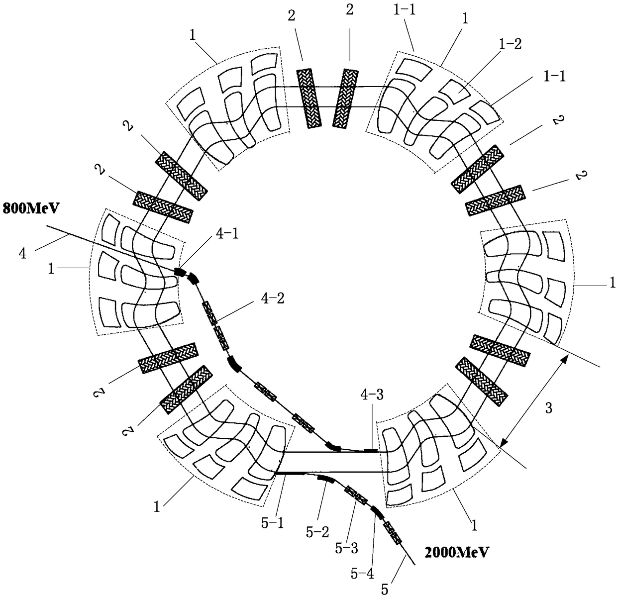
[0061] In this embodiment, a 3mA, 800MeV proton beam is injected into a high-energy, strong-current alternating gradient cyclotron, accelerated to 2GeV, and extracted. The average radii of the beam orbits of 800MeV and 2GeV are 16.28 meters and 18.33 meters, respectively. The minimum field strength of the focusing magnet is 1.76 Tesla, the maximum field strength is 2.60 Tesla, and the magnet width is 2.09 meters. The minimum field strength of the defocused magnet is 0.59 Tesla, the maximum field strength is 2.48 Tesla, and the magnet width is 1.82 meters. Two high-frequency accelerating cavities (a total of ten high-frequency cavities) are placed in each linear drift section, the frequency is 44.4MHz, and the beam energy gain per turn is 12MeV. The linear drift section length prepared for the beam extraction system is 10.52 meters. The radial and axial working points are respectively selected at 2.6 and 1.8. In this embodiment, a high-energy, strong-current alternating grad...


PUM


Abstract

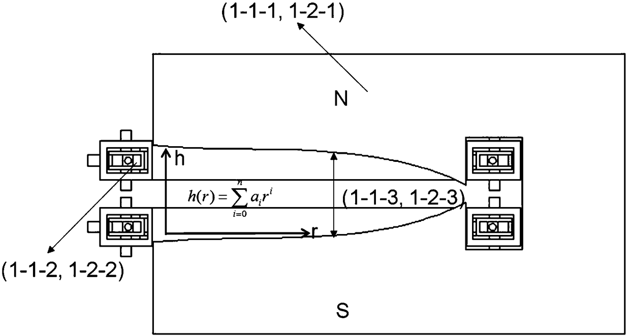
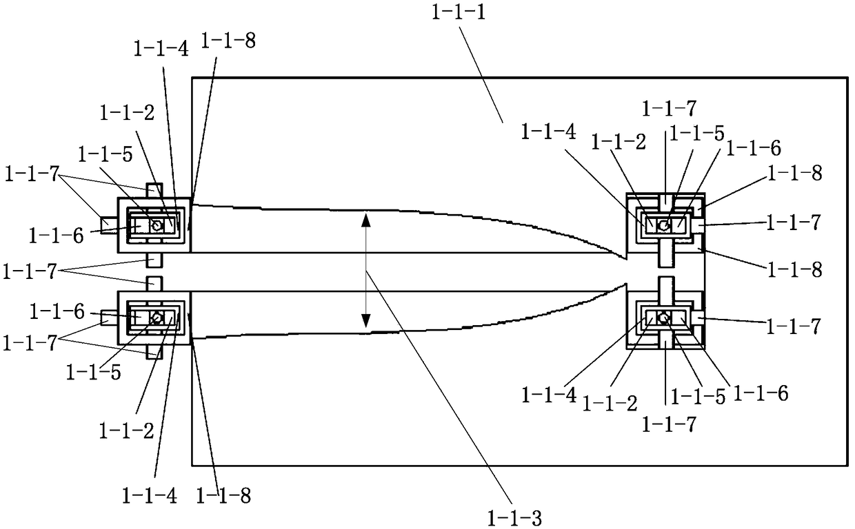
The invention discloses a high-energy and high-current alternating-gradient rotary accelerator which comprises a high-deflection magnetic field injection system, a high-deflection magnetic field extraction system, a plurality of periodic high-gradient torsional pendulum track generating magnet assemblies, a plurality of long drift sections, continuous beam acceleration wide-range variable-track magnet structures and high-power, high-stability and high-frequency acceleration systems. Axial focusing force can be generated by the periodic high-gradient torsional pendulum track generating magnet assemblies, the periodic high-gradient torsional pendulum track generating magnet assemblies are arranged along the circumferential direction of the high-energy and high-current alternating-gradient rotary accelerator, and the long drift sections are arranged between the magnet assemblies along the circumferential direction of the high-energy and high-current alternating-gradient rotary accelerator; the high-power, high-stability and high-frequency acceleration systems are arranged in the various long drift sections, and main rotary accelerator structures are formed by the high-power, high-stability and high-frequency acceleration systems and the periodic high-gradient torsional pendulum track generating magnet assemblies; particles can be injected into the high-energy and high-current alternating-gradient rotary accelerator by the injection system on the inner side of the certain drift section on an inner ring of the high-energy and high-current alternating-gradient rotary acceleratorand can be accelerated by main rotary accelerators, and beam currents can be ultimately extracted by the extraction system on the outer side of the certain drift section on an outer ring of the high-energy and high-current alternating-gradient rotary accelerator. The high-energy and high-current alternating-gradient rotary accelerator has the advantages that the high-energy and high-current alternating-gradient rotary accelerator is provided with periodic high-gradient torsional pendulum magnets, accordingly, the beam currents can be stably accelerated by higher than 1 GeV, and the limitationon energy of extracted beam currents of the traditional rotary accelerators can be broken through.

Description

technical field [0001] The invention belongs to the technical field of accelerators, in particular to a high-energy, strong-current alternating gradient cyclotron. Background technique [0002] In high-power proton accelerators (the power is represented by the product of current intensity and energy), the cyclotron scheme, the combination scheme of the linear accelerator and the fast cycle synchrotron are two schemes widely recognized internationally. For example, the 590MeV cyclotron at the Paul Scherrer Institute in Switzerland (power 1.3MeV, cyclotron scheme), my country’s China Spallation Neutron Source (beam energy 1.6GeV, power 0.1MW, a combination scheme of a linear accelerator and a fast cycle synchrotron ), the spallation neutron source in the United States (beam energy 1.0GeV, power 1.4MW, combination of linear accelerator and fast cycle synchrotron). [0003] The advantages of the cyclotron scheme are strong current, continuous beam, and low cost. The disadvantage...

Claims


Application Information

Patent Timeline
Patent Type & Authority Applications(China)
IPC IPC(8): H05H13/00H05H7/04
Inventor 张天爵李明边天剑王川安世忠殷治国王飞魏素敏纪彬
Owner CHINA INSTITUTE OF ATOMIC ENERGY
Why Eureka
Try Eureka