Powder spraying chamber with automatic gun collection beam inlet-outlet groove openings using dynamic sealing structures

A technology of dynamic sealing structure and automatic gun, which is applied in spray booths, spraying devices, etc., can solve the problems of rubber sheets that cannot be sealed, rubber sheets that are difficult to clean, and leaks, and achieve powder leakage that is not easy, cleaning is convenient, and the sealing effect is good. Effect

Pending Publication Date: 2019-02-22
YU TUNG ZHONGSHAN ENG
View PDF9 Cites 4 Cited by
  • Summary
  • Abstract
  • Description
  • Claims
  • Application Information

AI Technical Summary

Problems solved by technology

[0002] In the powder spraying room, the lifting mechanism of the automatic spray gun is usually set on the outside of the powder spraying room, and an opening for the automatic spray gun to be inserted and moved up and down should be opened on the side of the powder spraying room, which will cause a certain risk of leakage. For this problem, there are currently fixed films that can be closed or overlapped on both sides of the opening, and the spray gun passes between the two rubbers, but the film and the spray gun in this structure rub against each other, and the structure of the rubber film cannot be completely sealed. , and the rubber sheet is difficult to clean

Method used


Image

  • Powder spraying chamber with automatic gun collection beam inlet-outlet groove openings using dynamic sealing structures
  • Powder spraying chamber with automatic gun collection beam inlet-outlet groove openings using dynamic sealing structures
  • Powder spraying chamber with automatic gun collection beam inlet-outlet groove openings using dynamic sealing structures

Examples


Embodiment Construction

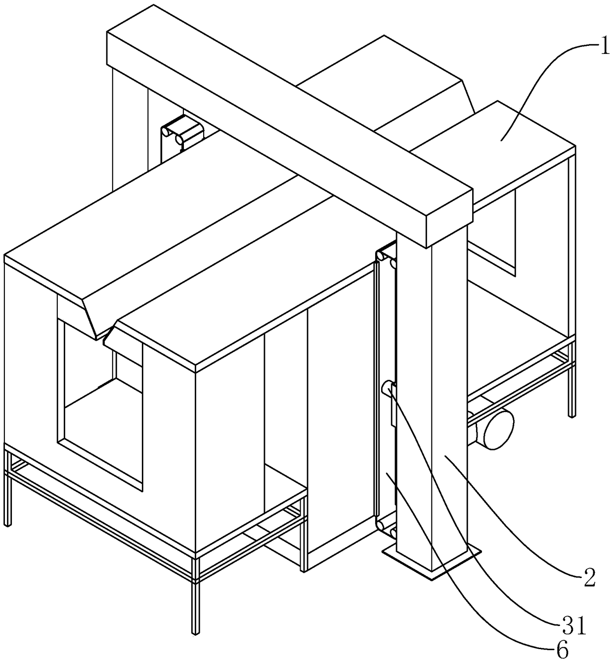
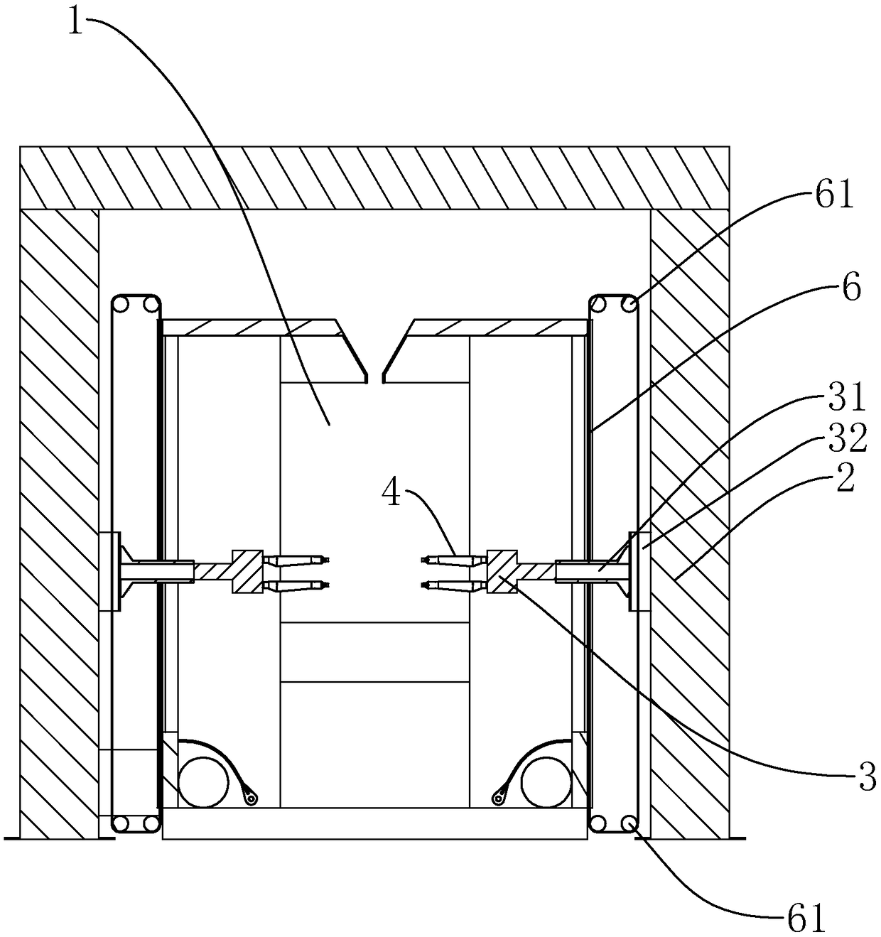
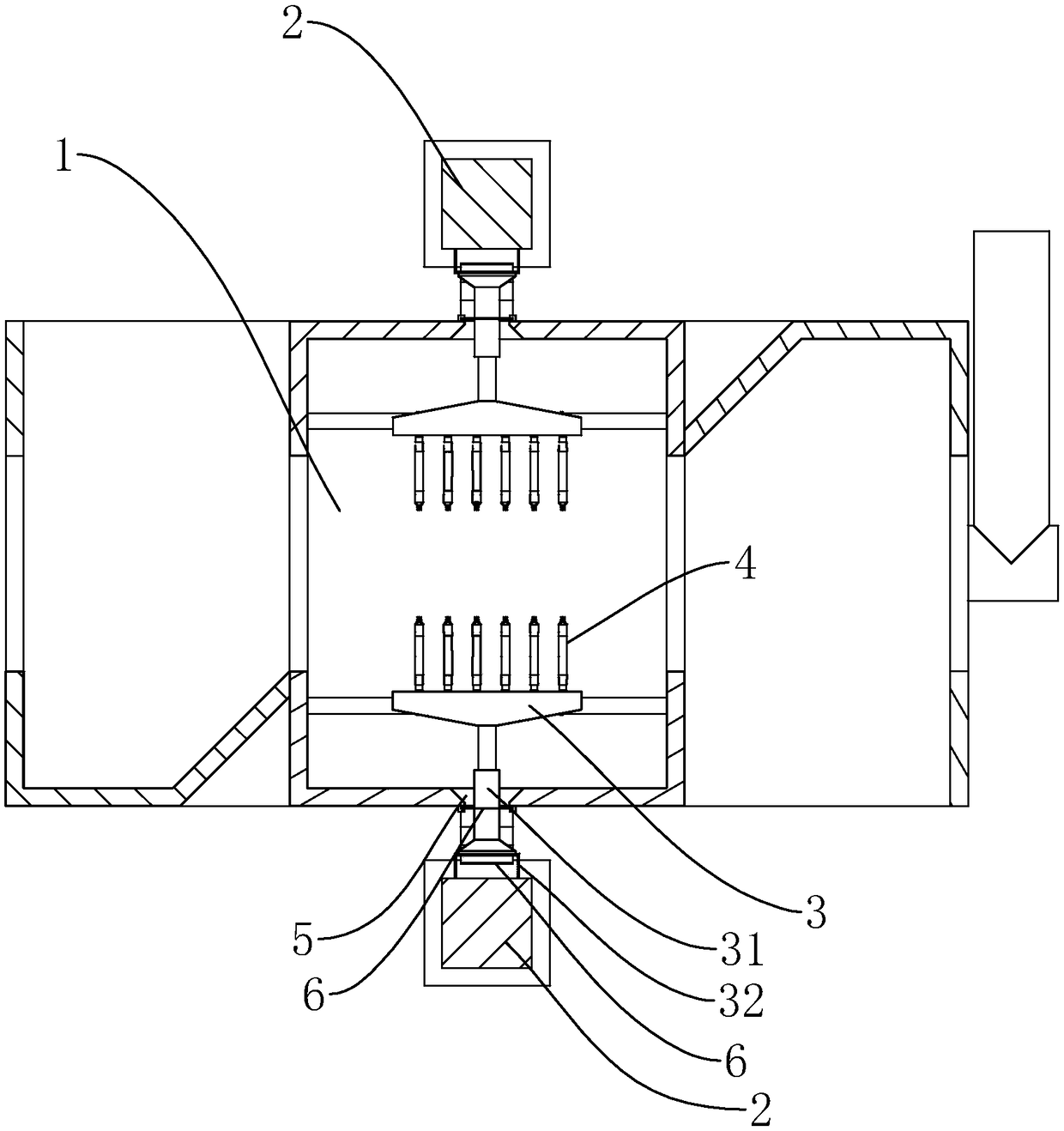
[0021] refer to Figure 1 to Figure 4 , Figure 1 to Figure 4 It is a structural schematic diagram of a specific embodiment of the present invention. As shown in the figure, a powder spraying room with a dynamic sealing structure for the inlet and outlet slots of the automatic gun collection beam includes a main body 1 of the spraying room and a powder spraying system. The powder spraying system includes An elevator 2 arranged on the outside of the main body 1 of the spraying room, an automatic gun collection beam 3 that can be driven up and down by the elevator 2, and a spray gun 4 arranged on the automatic gun collection beam 3, and the automatic gun collection beam 3 passes through a connecting rod 31 is connected to the lifter 2, on the side wall of the spray booth main body 1, there is a long entry and exit slot 5 that can pass through the connecting rod 31, and the entry and exit slot 5 provides the up and down reciprocating movement of the connecting rod 31 required sp...


PUM


Abstract

The invention discloses a powder spraying chamber with automatic gun collection beam inlet-outlet groove openings using dynamic sealing structures. The powder spraying chamber comprises a spraying chamber main body and a powder spraying system, wherein the powder spraying system comprises lifting machines, automatic gun collection beams and spraying guns; the automatic gun collection beams are connected with the lifting machines through connection rods; inlet-outlet groove openings are formed in the side wall of the spraying chamber main body and are used for providing space needed for up-and-down reciprocating motion of the connection rods; inlet-outlet groove opening sealing devices are arranged on the inlet-outlet groove openings; the inlet-outlet groove opening sealing devices are flexible sealing tapes using dynamic sealing structure manners; through holes for penetration of the connection rods are formed in the flexible sealing tapes; the flexible sealing tapes are used for sealing the inlet-outlet groove openings in the side wall of the spraying chamber main body and an air flowing path outside the spraying chamber main body; the flexible sealing tapes are capable of movingalong the automatic gun collection beams and achieving dynamic sealing. The powder spraying chamber is excellent in sealing effect, low in possibility of powder leakage and relatively convenient to clean.

Description

technical field [0001] The invention relates to the field of spraying, in particular to a powder spraying chamber in which the inlet and outlet slots of the collecting beam of an automatic gun adopt a dynamic sealing structure. Background technique [0002] In the powder spraying room, the lifting mechanism of the automatic spray gun is usually set on the outside of the powder spraying room, and an opening for the automatic spray gun to be inserted and moved up and down should be opened on the side of the powder spraying room, which will cause a certain risk of leakage. For this problem, there are currently fixed films that can be closed or overlapped on both sides of the opening, and the spray gun passes between the two rubbers, but the film and the spray gun in this structure rub against each other, and the structure of the rubber film cannot be completely sealed. , At the same time, it is difficult to clean the rubber sheet. Contents of the invention [0003] In order ...

Claims


Application Information

Patent Timeline
Patent Type & Authority Applications(China)
IPC IPC(8): B05B16/40B05B13/04
CPCB05B13/041B05B16/40
Inventor 高敏坚柯儒群
Owner YU TUNG ZHONGSHAN ENG
Why Eureka
Try Eureka