
Auxiliary frame crescent hole forming equipment

A technology for forming equipment and sub-frames, applied in metal processing equipment, perforating tools, vehicle parts, etc., can solve problems such as low efficiency, poor position accuracy, and slow speed, so as to ensure position accuracy, improve product quality, and improve processing efficiency effect

Pending Publication Date: 2019-02-22
苏州托克斯冲压设备有限公司
View PDF0 Cites 0 Cited by
  • Summary
  • Abstract
  • Description
  • Claims
  • Application Information

AI Technical Summary

Problems solved by technology

However, the shape of some automobile chassis frames is extremely irregular. In many cases, there is no space for punching devices. It is forced to process the mounting holes on the bracket before welding, and then weld the bracket to the designated position on the chassis. Due to the dual effects of secondary clamping positioning and welding deformation, the position accuracy of the hole position relative to the entire automobile chassis frame is very poor, which seriously affects the stability of the entire vehicle.
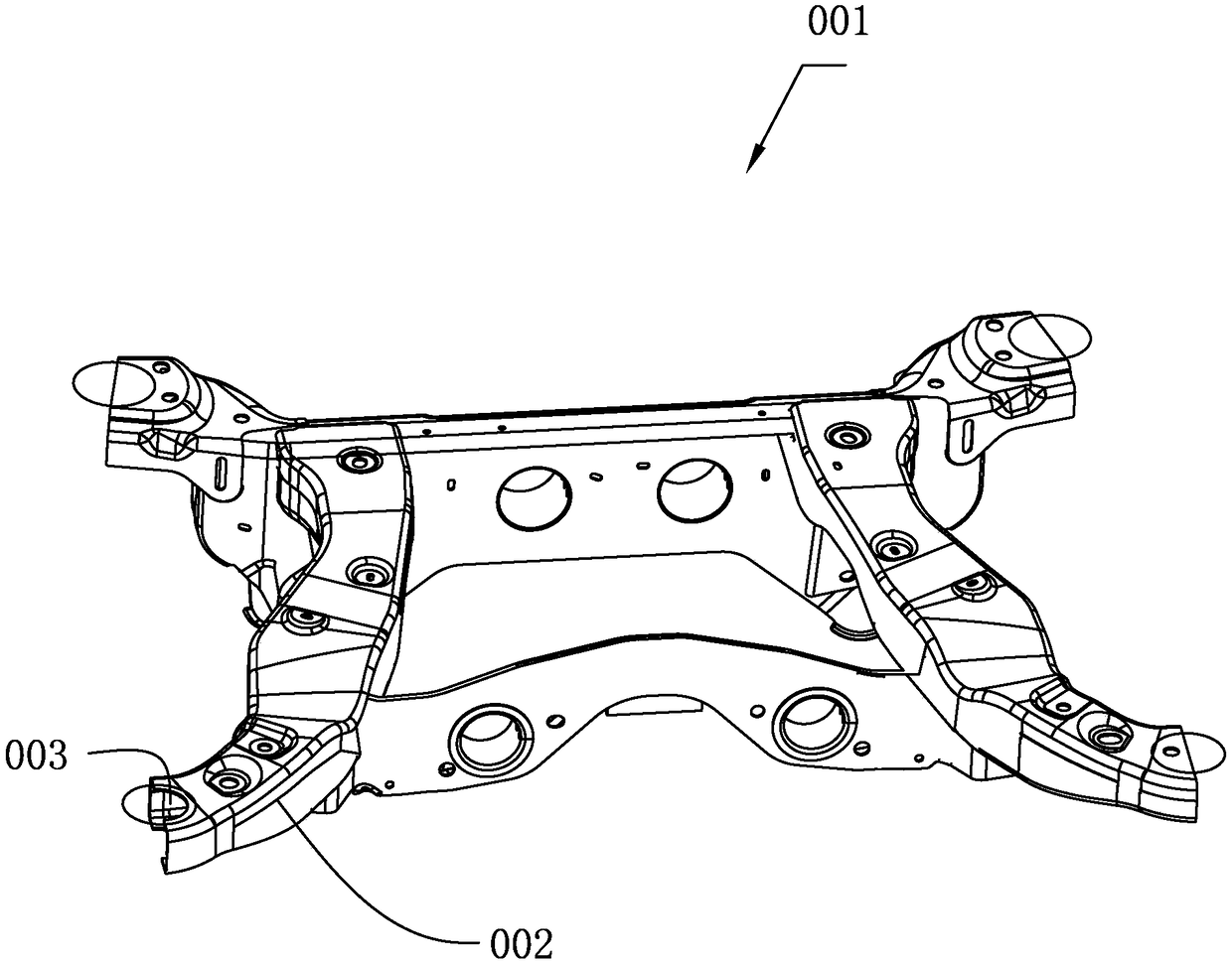
like figure 1 As shown, the ends of the four outwardly extending arms of a subframe need to be processed with semicircular holes (the upper and lower plates of one arm need to be processed with semicircular holes). In the prior art, the semicircular holes are punched out first. However, the sub-frame is formed after welding each component, so the position accuracy of the punched out semicircular hole is difficult to guarantee, and the ends of the four connecting arms are punched separately, which is slow and inefficient

Method used


Image

  • Auxiliary frame crescent hole forming equipment
  • Auxiliary frame crescent hole forming equipment
  • Auxiliary frame crescent hole forming equipment

Examples


Embodiment Construction

[0024] The present invention will be described in further detail below in conjunction with the accompanying drawings and specific embodiments.

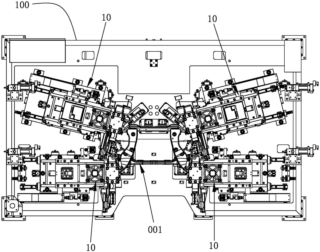
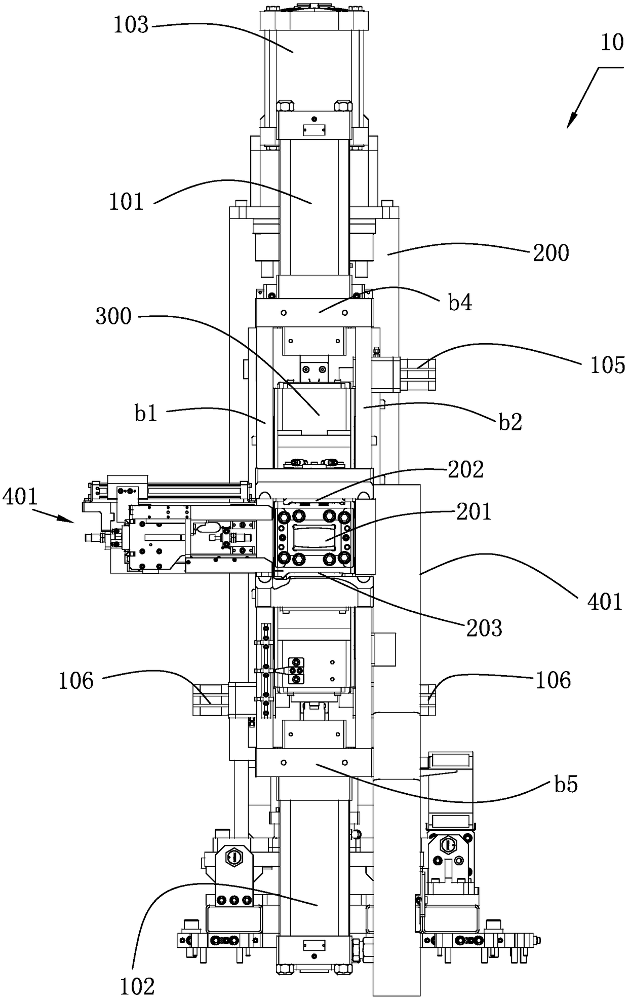
[0025] like Figure 1 to Figure 6 As shown, a forming device for the crescent hole of the sub-frame, the forming device is used for synchronously punching and forming the crescent holes 003 at the ends of a plurality of connecting arms 002 of the sub-frame 001, the forming device includes an equipment rack 100, a sliding The multiple groups of punching units 10 arranged on the equipment frame 100, the positioning frame for fixing the auxiliary frame 001 fixedly arranged on the equipment frame 100 and between the multiple groups of punching units 10, and controlling the operation of the punching units 10 control system, the equipment frame 100 is provided with multiple sets of slide rails, and each set of punching unit 10 includes a sliding support frame 200 arranged on the slide rails, and a tool for punching the crescent hole 003 on ...


PUM


Abstract

The invention relates to auxiliary frame crescent hole forming equipment. The forming equipment is used for conducting punching forming on crescent holes in the ends of multiple connection arms of anauxiliary frame synchronously; the forming equipment comprises an equipment frame, a plurality of punching units slidably arranged on the equipment frame, a positioning frame which is fixedly arrangedon the equipment frame, located between the multiple punching units and used for fixing the auxiliary frame, and a control system for controlling the punching units to work; the equipment frame is provided with a plurality of sets of slide rails; each punching unit comprises a supporting frame slidably arranged on the corresponding slide rail, and a punching module which is arranged on the supporting frame and used for crescent hole punching. The auxiliary frame crescent hole forming equipment can simultaneously conduct post-welding synchronous punching on the ends of the four connection armsof the auxiliary frame, the situation that the connection arms are subjected to punching machining in sequence is avoided, the machining efficiency is greatly improved, in addition, the position precision of the crescent holes on the auxiliary frame is ensured, and the product quality is improved.

Description

technical field [0001] The invention relates to a forming device for a crescent hole of an auxiliary frame. Background technique [0002] At present, when processing the hole position of the front / rear sub-frame of the automobile chassis, the method of punching after welding is mainly used for the front / rear sub-frame of the automobile chassis with a relatively regular shape, because it can obtain better hole position accuracy. However, the shape of some automobile chassis frames is extremely irregular. In many cases, there is no space for punching devices. It is forced to process the mounting holes on the bracket before welding, and then weld the bracket to the designated position on the chassis. Due to the dual effects of secondary clamping positioning and welding deformation, the position accuracy of the hole position relative to the entire automobile chassis frame is very poor, which seriously affects the stability of the entire vehicle. like figure 1 As shown, the end...

Claims


Application Information

Patent Timeline
IPC IPC(8): B21D28/32B21D28/34B21D53/88
CPCB21D28/002B21D28/32B21D28/34B21D53/88
Inventor 朴澈雨
Owner 苏州托克斯冲压设备有限公司
Learn More