End removal device for solid metal connection

A solid-state connection, head and tail technology, which is applied in the field of metal solid-state connection removal head and tail devices, can solve the problems of long connection time, short connection time, and disadvantageous endless rolling transformation of old rolling mills, and achieves the effect of high cutting efficiency.

Pending Publication Date: 2019-02-22
HEBEI UNIVERSITY OF SCIENCE AND TECHNOLOGY
View PDF2 Cites 2 Cited by
  • Summary
  • Abstract
  • Description
  • Claims
  • Application Information

AI Technical Summary

Problems solved by technology

[0003] However, the induction welding and laser welding connection of conventional intermediate billets takes a long time, which is not conducive to the endless rolling transformation of old rolling mills. Document ZL201410019608.9 invented a method of shearing and extrusion to realize the connection of intermediate billets, which has the advantages of The short connection time is beneficial to the endless rolling transformation of old rolling mills. On this basis, document ZL201410658589.4 invented a quick connection mechanism for intermediate blanks, which is used for online dynamic connection of intermediate blanks. This invention has the advantages of short connection time It is very beneficial to the endless rolling transformation of the old rolling line
However, there is a problem in the above two inventions, that is, after the connection is completed, there will be a head and tail in the connected intermediate billet, which is not conducive to the next step of online continuous rolling

Method used


Image

  • End removal device for solid metal connection
  • End removal device for solid metal connection
  • End removal device for solid metal connection

Examples


Embodiment Construction

[0027] In order to detail the technical content, structural features, achieved goals and effects of the present invention, the following will be described in detail in conjunction with the accompanying drawings.

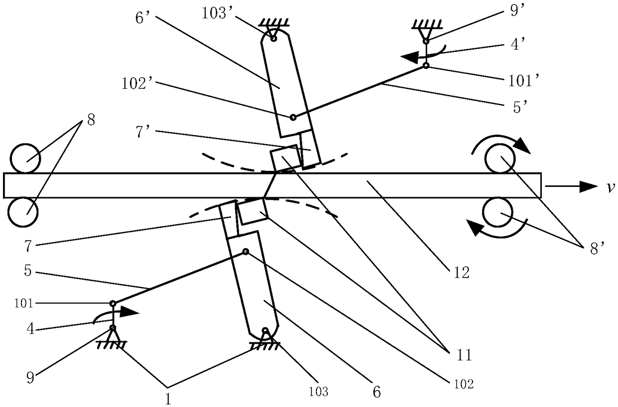
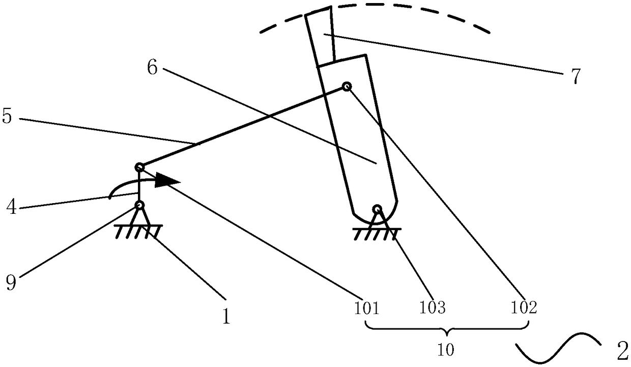
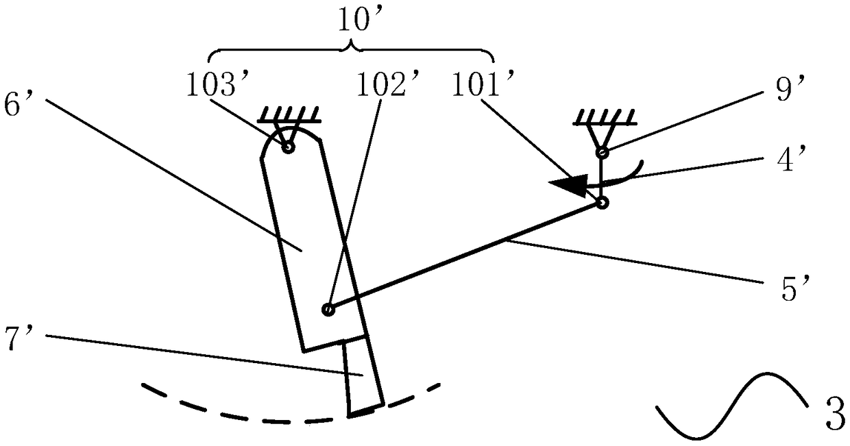
[0028] The present invention provides a metal solid connection removal head and tail device, such as Figure 1~3 As shown, including a frame 1, a first cutting device 2, a second cutting device 3, driving rollers 8, 8' and a driving device 16, the first cutting device 2 and the second cutting device 3 are installed on the frame 1 , and the structure is the same, all including crank 4, 4', connecting rod 5, 5', rocker 6, 6', cutter head 7, 7', drive shaft 9, 9' and connecting hinge 10, 10', the first The first end of the crank 4 of a cutting device 2 is provided with a drive shaft 9, and the drive shaft 9 is hinged on the frame 1, and the first end of the connecting rod 5 is connected with the second end of the crank 4 through the first connecting hinge 101. The firs...


PUM


Abstract

The invention discloses an end removal device for solid metal connection. The end removal device comprises a rack, a first cutting device, a second cutting device, a drive roller and a driving device,wherein the first cutting device and the second cutting device are mounted on the rack, and each of the first cutting device and the second cutting device comprises a crankshaft, a connecting rod, arocker, a tool bit, a drive shaft and a connecting hinge; in the first cutting device, the drive shaft arranged at a first end of the crankshaft is hinged to the rack, a first end of the connecting rod is hinged to a second end of the crankshaft, a first end of the rocker is hinged to the rack, a second end of the rocker is hinged to a second end of the connecting rod, and the tool bit is fixedlyconnected to a second end surface of the rocker; and the driving device comprises a motor, a first coupler, a reducer and a second coupler, an input end of the reducer is fixedly connected to the motor through the first coupler, and an output shaft of the reducer is fixedly connected to the drive shaft through the second coupler. The end removal device can quickly remove ends generated after solidconnection of metal plates to guarantee uninterrupted rolling of the metal plates, and therefore, lays a foundation for realizing endless rolling.

Description

technical field [0001] The invention relates to a head and tail removal device for metal solid state connection. The device is used for removing the head and tail of intermediate blanks connected online, so as to facilitate smooth rolling. Background technique [0002] With the development of science and technology, people have higher and higher requirements for new materials, and modern metal connection technology mainly includes metallurgical connection, commonly known as welding, mechanical connection, and chemical connection, among which welding technology is dominant and the most widely used. In 1991, the British Welding Institute invented a new solid-state connection technology - friction stir welding, referred to as FSW. The internal stress and deformation of the joint after welding are small, and the low-stress and deformation-free welding of the plate can basically be realized, which has become a new type of green welding technology. The metal solid state connectio...

Claims


Application Information

Patent Timeline
Patent Type & Authority Applications(China)
IPC IPC(8): B23D79/00
CPCB23D79/00
Inventor 姚云峰张双杰李强
Owner HEBEI UNIVERSITY OF SCIENCE AND TECHNOLOGY
Why Eureka
Try Eureka