Plastic gear sander

A technology of plastic gears and grinders, which is applied in the direction of belts/chains/gears, gear teeth, and components with teeth, etc. It can solve the problems of grinding the corners of difficult plastic gears and easy sore arms, so as to improve the grinding efficiency. Easy to polish effect

Active Publication Date: 2019-02-22
南通市科脉电子科技有限公司
View PDF4 Cites 5 Cited by
  • Summary
  • Abstract
  • Description
  • Claims
  • Application Information

AI Technical Summary

Problems solved by technology

[0003] In order to overcome the shortcoming that people use hand-held grinding sticks to polish the corners of plastic gears for a long time, the arms are prone to soreness, and it is difficult to completely polish the corners of plastic gears. Therefore, the technical problem of the present invention is: to provide a method that can prevent Sore Arms, Plastic Gear Grinders for Handy Grinding

Method used


Image

  • Plastic gear sander
  • Plastic gear sander
  • Plastic gear sander

Examples


Embodiment 1

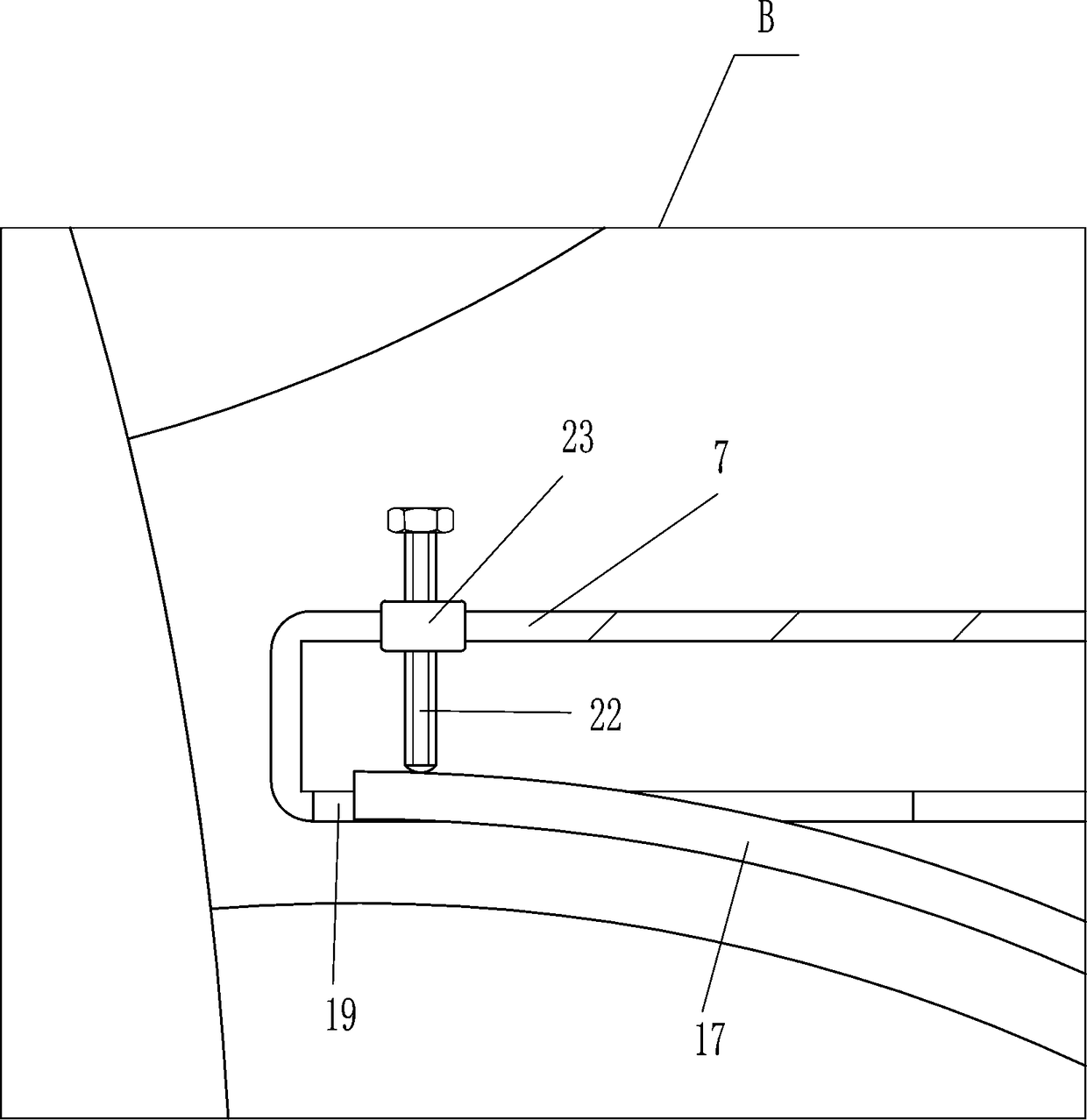
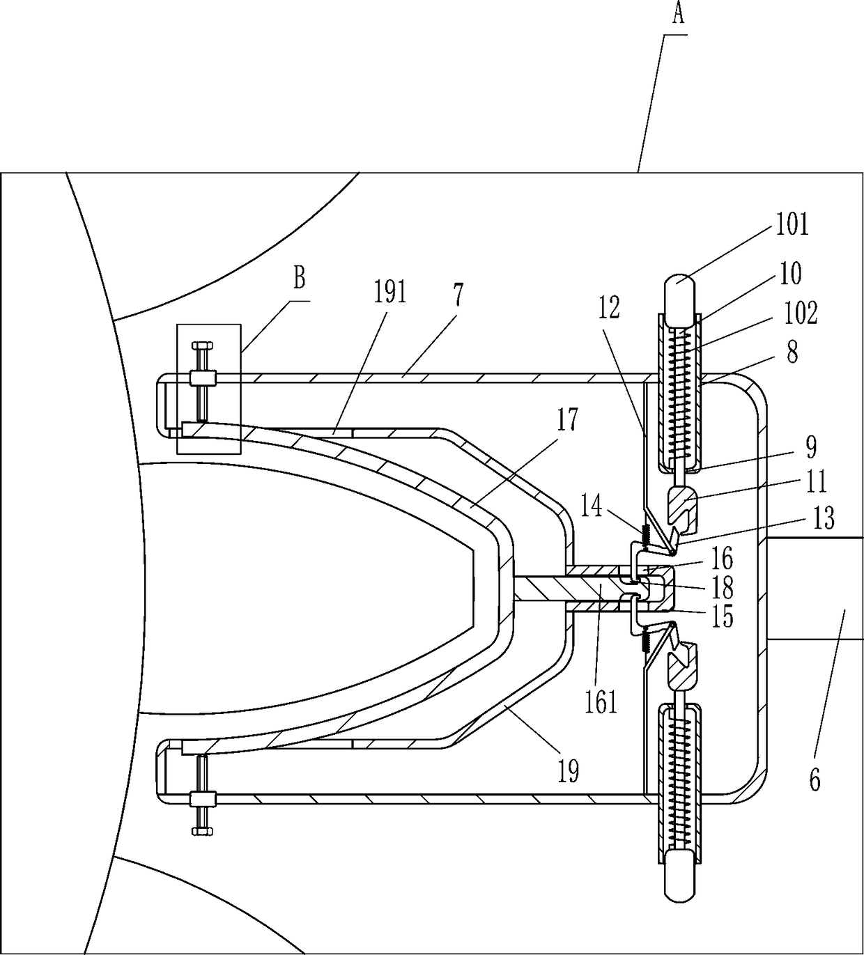
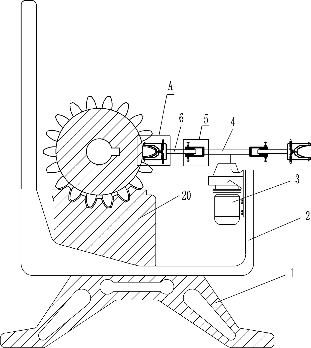
[0021] A plastic gear grinder such as Figure 1-5 As shown, it includes a support 1, a U-shaped frame 2, a motor 3, a turntable 4, an adjustment device 5, a connecting plate 6, a hollow frame 7, a first hollow tube 8, a first guide rod 10, a pressing block 101, a first Spring 102, groove block 11, pole 12, swing clamp 13, second spring 14, second hollow tube 15, slide bar 161, polishing plate 17, mounting plate 19 and placement seat 20, U-shaped frame 2 is fixed on The top of the bearing 1 supporting the function, the motor 3 is installed on the upper right wall in the U-shaped frame 2, the top of the output shaft of the motor 3 is fixedly equipped with a turntable 4, and there are two adjustment devices 5, which are installed on the left and right sides of the turntable 4 respectively. On the side, the connecting plate 6 is fixedly connected to the adjusting device 5, and the hollow frame 7 is fixedly installed on the connecting plate 6. There are four first hollow tubes 8, w...

Embodiment 2

[0023] A plastic gear grinder such as Figure 1-5As shown, it includes a support 1, a U-shaped frame 2, a motor 3, a turntable 4, an adjustment device 5, a connecting plate 6, a hollow frame 7, a first hollow tube 8, a first guide rod 10, a pressing block 101, a first Spring 102, groove block 11, pole 12, swing clamp 13, second spring 14, second hollow tube 15, slide bar 161, polishing plate 17, mounting plate 19 and placement seat 20, U-shaped frame 2 is fixed on The top of the bearing 1 supporting the function, the motor 3 is installed on the upper right wall in the U-shaped frame 2, the top of the output shaft of the motor 3 is fixedly equipped with a turntable 4, and there are two adjustment devices 5, which are installed on the left and right sides of the turntable 4 respectively. On the side, the connecting plate 6 is fixedly connected to the adjusting device 5, and the hollow frame 7 is fixedly installed on the connecting plate 6. There are four first hollow tubes 8, wh...

Embodiment 3

[0026] A plastic gear grinder such as Figure 1-5 As shown, it includes a support 1, a U-shaped frame 2, a motor 3, a turntable 4, an adjustment device 5, a connecting plate 6, a hollow frame 7, a first hollow tube 8, a first guide rod 10, a pressing block 101, a first Spring 102, groove block 11, pole 12, swing clamp 13, second spring 14, second hollow tube 15, slide bar 161, polishing plate 17, mounting plate 19 and placement seat 20, U-shaped frame 2 is fixed on The top of the bearing 1 supporting the function, the motor 3 is installed on the upper right wall in the U-shaped frame 2, the top of the output shaft of the motor 3 is fixedly equipped with a turntable 4, and there are two adjustment devices 5, which are installed on the left and right sides of the turntable 4 respectively. On the side, the connecting plate 6 is fixedly connected to the adjusting device 5, and the hollow frame 7 is fixedly installed on the connecting plate 6. There are four first hollow tubes 8, w...


PUM


Abstract

The invention relates to a sander, in particular to a plastic gear sander; therefore, the invention aims to solve the technical problem that the plastic gear sander which is capable of preventing armsfrom aching pain and can be used for conveniently sanding a plastic gear is not provided. The technical solution of the invention is that the plastic gear sander comprises a support seat, a U-shapedrack, a motor, a rotating disc, adjusting devices, connecting plates, hollow frames, first hollow pipes, first guide rods, pressing blocks and the like; the U-shaped rack is fixedly arranged at the top part of the support seat playing a role of supporting; the motor is arranged at the upper part of the right wall in the U-shaped rack; the top end of the output shaft of the motor is fixedly provided with the rotating disc; the adjusting devices are arranged by two, and are correspondingly arranged at the left side and the right side of the rotating disc; and each adjusting plate is fixedly connected with the corresponding connecting plate. According to the plastic gear sander disclosed by the invention, each hollow frame is adjusted in position by the corresponding adjusting device; a sanding plate rotates and is in contact with teeth of the plastic gear, and therefore, the teeth of the plastic gear can be sanded; and sanding of the plastic gear can be facilitated by the replacement wayof the sanding plate, and then, the sanding efficiency of the plastic gear can be increased.

Description

technical field [0001] The invention relates to a grinder, in particular to a plastic gear grinder. Background technique [0002] After the injection molding of the plastic gear is completed, the corners of the plastic gear need to be polished. At present, when polishing the plastic gear, people usually use a hand-held grinding bar to polish the corners of the plastic gear. Because the corners of the plastic gear are relatively narrow, It is so difficult to grind the corners of plastic gears thoroughly, and people tend to have sore arms after grinding plastic gears for a long time. In order to prevent arm soreness, people install grinding bars on the motor, and then people hold plastic gears for grinding. Thereby will increase people's labor intensity. Contents of the invention [0003] In order to overcome the shortcoming that people use hand-held grinding sticks to polish the corners of plastic gears for a long time, their arms are prone to soreness, and it is difficult...

Claims


Application Information

Patent Timeline
Patent Type & Authority Applications(China)
IPC IPC(8): B23F19/02
CPCB23F19/02
Inventor 萧夏琴
Owner 南通市科脉电子科技有限公司
Why Eureka
Try Eureka