
Clamping device used for lock machining

A clamping device and lock technology, applied in positioning devices, metal processing equipment, metal processing mechanical parts, etc., can solve the problems of cumbersome clamping equipment, unfavorable batch processing, high production cost, etc., and achieve convenient drilling process, use Safe and convenient, the effect of improving the accuracy of processing

Inactive Publication Date: 2019-02-22
池州市安安新材科技有限公司
View PDF0 Cites 1 Cited by
  • Summary
  • Abstract
  • Description
  • Claims
  • Application Information

AI Technical Summary

Problems solved by technology

[0003] Most of the clamping equipment currently on the market is cumbersome and complicated, which is not conducive to batch processing, and most of the clamping equipment is specific. For many different parts, a variety of different clamping equipment is required, and the production cost is huge. If there is one A clamping device with universal applicability can be put into production in the clamping equipment of different lock parts, which can greatly improve production efficiency and reduce processing costs

Method used


Image

  • Clamping device used for lock machining
  • Clamping device used for lock machining
  • Clamping device used for lock machining

Examples


Embodiment Construction

[0027] The following will clearly and completely describe the technical solutions in the embodiments of the present invention with reference to the accompanying drawings in the embodiments of the present invention. Obviously, the described embodiments are only some, not all, embodiments of the present invention. Based on the embodiments of the present invention, all other embodiments obtained by persons of ordinary skill in the art without making creative efforts belong to the protection scope of the present invention.

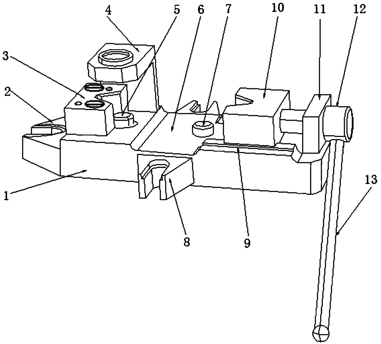
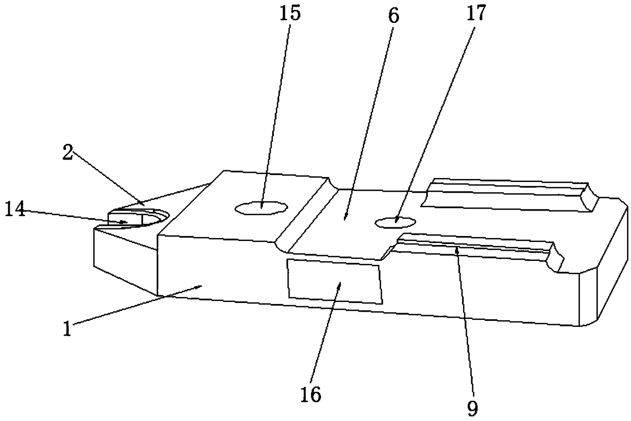
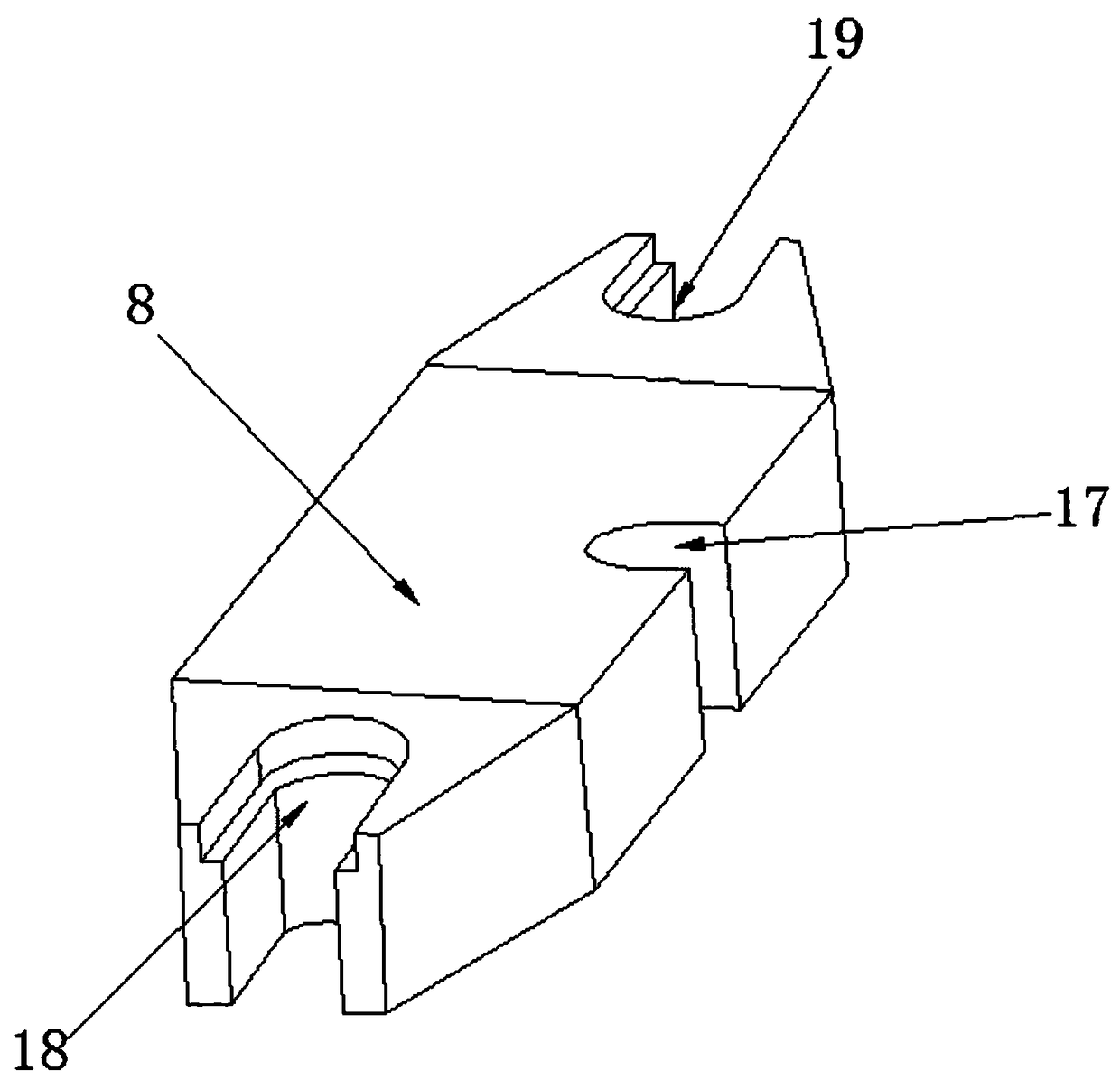
[0028] see Figure 1-7 , in an embodiment of the present invention, a clamping device for lock processing includes a base 1, one end side of the base 1 is fixed to the side of the first fixed frame 2, a positioning block 3 is installed on the upper surface of one end of the base 1, and the positioning block 3 The rear side of the operating frame 4 is installed, the bottom surface of the operating frame 4 is fixedly connected to the upper surface of the base 1,...


PUM


Abstract

The invention discloses a clamping device used for lock machining. The device comprises a base, the side face of one end of the base fixes the side face of a first fixed frame, a positioning block isarranged on the upper surface of one end of the base, a positioning pin is arranged in a concave opening of the positioning block, a chip removal groove is formed in the middle segment of the upper surface of the base, a guide rail is fixedly arranged on the other end of the upper surface of the base, and a sliding block is arranged at the upper end of the guide rail. The positioning block with apositioning clamping opening and a sliding block with a sliding clamping opening are arranged, the clamping device can stably clamp more parts, and the device is suitable for machining of locks in different shapes, the positioning pin, a guide pin and a limiting block are arranged, the fixed clamping device can achieve precise positioning while clamping is achieved, replacement is convenient, dismounting and mounting are rapid, the industrial needs of precise lock machining can be met, a fixed frame is arranged to form a triangular stable frame, and a stable foundation is provided for variousprocedures of part machining.

Description

technical field [0001] The invention relates to the field of lock processing, in particular to a clamping device for lock processing. Background technique [0002] At present, in the process of processing each part in the lock, there are many procedures for making, drilling, assembling and connecting each part, and for different parts, clamping equipment needs to be stably clamped before proceeding to the next specific process, and at the same time, the positioning must be ensured Precise, the positions of the holes connected between the parts correspond, so many specifications are required in the positioning process. [0003] Most of the clamping equipment currently on the market is cumbersome and complicated, which is not conducive to batch processing, and most of the clamping equipment is specific. For many different parts, a variety of different clamping equipment is required, and the production cost is huge. If there is one A clamping device with universal applicabilit...

Claims


Application Information

Patent Timeline
Patent Type & Authority Applications(China)
IPC IPC(8): B23Q3/06
CPCB23Q3/062
Inventor 刘沛峰项泽元黄进
Owner 池州市安安新材科技有限公司
Learn More